IMU-3000 INVENSENSE, IMU-3000 Datasheet - Page 35

IMU-3000
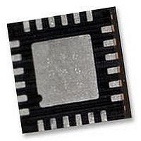
Manufacturer Part Number
IMU-3000
Description
GYRO, TRI-AXIS, PROG +/-2000 DEG/S
Manufacturer
INVENSENSE
Datasheet
1.IMU-3000.pdf
(56 pages)
Specifications of IMU-3000
No. Of Axes
3
Sensor Case Style
QFN
No. Of Pins
24
Supply Voltage Range
2.1V To 3.6V
Operating Temperature Range
-40°C To +85°C
Interface
I2C, Serial
Interface Type
I2C, Serial
Rohs Compliant
Yes
Lead Free Status / RoHS Status
Lead free / RoHS Compliant
10.8 Register 23 – Interrupt Configuration
10.9 Register 24 – AUX (Accel) Burst Read Address / Secondary I
Type: Read/Write
Description:
This register configures the interrupt operation of the IMU-3000. The interrupt output pin (INT)
configuration can be set, the interrupt latching/clearing method can be set, and the triggers for the
interrupt can be set. If LATCH_INT_EN = 1, the INT pin is held active until the interrupt status
register is cleared.
Note that if the application requires reading every sample of data from the IMU-3000, it is best to
enable the raw data ready interrupt (RAW_RDY_EN). This allows the application to know when new
sample data is available.
Parameters:
ACTL
OPEN
LATCH_INT_EN
INT_ANYRD_2CLEAR Interrupt status register clear method – 1=clear by reading any register,
I2C_MST_ERR_EN
IMU_RDY_EN
DMP_DONE_EN
RAW_RDY_EN
Type: Read/Write
Description:
This register configures the burst-mode-read starting address for an accelerometer attached to the
secondary I
clock and data lines (AUX_CL, AUX_DA).
Parameters:
AUX_VDDIO
BURST_ADDR
Register
Register
(Hex)
(Hex)
17
18
(Decimal)
(Decimal)
2
Register
Register
C bus of the IMU-3000, and determines the I/O logic levels of the secondary I
23
24
IMU-3000 Product Specification
I/O logic levels for the secondary I
AUX_DA; 1=VDD, 0=VLOGIC)
Burst-mode-read starting address for external accelerometer attached to
secondary I
ACTL
Bit7
Logic level for INT output pin – 1=active low, 0=active high
Drive type for INT output pin – 1=open drain, 0=push-pull
Latch mode – 1=latch until interrupt is cleared, 0=50µs pulse
0=clear by reading interrupt status register (26) only
Enable interrupt when accelerometer on secondary I
acknowledge IMU-3000
Enable interrupt when device is ready (PLL ready after changing clock
source)
Enable interrupt when DMP is done (programmable functionality)
Enable interrupt when data is available
Bit7
OPEN
Bit6
2
C bus of the IMU-3000.
Bit6
35 of 56
LATCH_
INT_EN
Bit5
Bit5
ANYRD_
2CLEAR
INT_
Bit4
BURST_ADDR
Bit4
2
C bus clock and data lines (AUX_CL,
I2C_MST
_ERR_E
Bit3
N
2
C Bus I/O Level
Bit3
Document Number: PS-IMU-3000A-00-01.1
Revision: 1.1
Release Date: 08/19/2010
RDY_
IMU_
Bit2
EN
Bit2
2
C bus does not
DONE
DMP_
Bit1
_EN
Bit1
RAW_
RDY_
Bit0
Bit0
EN
2
C bus
Default
Default
Value
Value
00h
00h


