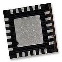
IMU-3000 INVENSENSE, IMU-3000 Datasheet - Page 42

IMU-3000
Manufacturer Part Number
IMU-3000
Description
GYRO, TRI-AXIS, PROG +/-2000 DEG/S
Manufacturer
INVENSENSE
Datasheet
1.IMU-3000.pdf
(56 pages)
Specifications of IMU-3000
No. Of Axes
3
Sensor Case Style
QFN
No. Of Pins
24
Supply Voltage Range
2.1V To 3.6V
Operating Temperature Range
-40°C To +85°C
Interface
I2C, Serial
Interface Type
I2C, Serial
Rohs Compliant
Yes
Lead Free Status / RoHS Status
Lead free / RoHS Compliant
10.16 Register 62 – Power Management
Type: Read/Write
Description:
This register is used to manage the power control, select the clock source, and to issue a master
reset to the device.
H_RESET is used to reset the device and set the internal registers to the power-up default settings.
STBY_XG, STBY_YG, and STBY_ZG are used to place the gyros into a standby or active mode
(1=standby; 0=normal operating mode).
Setting the SLEEP bit in the register puts the device into a low power sleep mode. In this mode, only
the serial interface and internal registers remain active, allowing for a very low standby current.
Clearing this bit puts the device back into normal mode. The individual standby selections for each
of the gyros should be used if any of them are not used by the application.
The CLK_SEL setting determines the device clock source as follows:
On power up, the IMU-3000 defaults to the internal oscillator. It is highly recommended that the
device is configured to use one of the gyros (or an external clock) as the clock reference, due to the
improved stability.
Parameters:
H_RESET
SLEEP
STBY_XG
STBY_YG
STBY_ZG
CLK_SEL
Register
(Hex)
3E
(Decimal)
Register
62
CLK_SEL
CLK_SEL
Reset device and internal registers to the power-up-default settings
Enable low power sleep mode
Put gyro X in standby mode (1=standby, 0=normal)
Put gyro Y in standby mode (1=standby, 0=normal)
Put gyro Z in standby mode (1=standby, 0=normal)
Select device clock source
H_RESET
IMU-3000 Product Specification
0
1
2
3
4
5
6
7
Bit7
Clock Source
Internal oscillator
PLL with X Gyro reference
PLL with Y Gyro reference
PLL with Z Gyro reference
PLL with external 32.768kHz reference
PLL with external 19.2MHz reference
Reserved
Stop clock and synchronous reset clock state
SLEEP
Bit6
42 of 56
STBY
_XG
Bit5
STBY
Bit4
_YG
STBY
_ZG
Bit3
Document Number: PS-IMU-3000A-00-01.1
Revision: 1.1
Release Date: 08/19/2010
Bit2
CLK_SEL
Bit1
Bit0
Default
Value
00h


