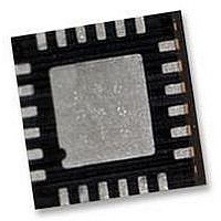
IMU-3000 INVENSENSE, IMU-3000 Datasheet - Page 32

IMU-3000
Manufacturer Part Number
IMU-3000
Description
GYRO, TRI-AXIS, PROG +/-2000 DEG/S
Manufacturer
INVENSENSE
Datasheet
1.IMU-3000.pdf
(56 pages)
Specifications of IMU-3000
No. Of Axes
3
Sensor Case Style
QFN
No. Of Pins
24
Supply Voltage Range
2.1V To 3.6V
Operating Temperature Range
-40°C To +85°C
Interface
I2C, Serial
Interface Type
I2C, Serial
Rohs Compliant
Yes
Lead Free Status / RoHS Status
Lead free / RoHS Compliant
10.5 Register 20 – AUX (Accel) Slave Address
10.6 Register 21 – Sample Rate Divider
Type: Read/Write
Description:
This register contains the enable bit for the reference clock output and the 7-bit slave address of the
external 3
The CLKOUTEN bit is used to enable (1) or disable (0) the reference clock output at the CLKOUT
pin.
AUX_ID, the 7-bit accelerometer slave address, is used to access the accelerometer so that its
sensor reading can be automatically read during each sample period at the same time as the gyro
sensors.
When reading the external accelerometer registers, the IMU-3000 takes over the secondary I
as a master to the accel, performing a burst read of the sensor registers. For this interface to be
active, the AUX_IF_EN flag in the User Control register (61) must be set (set to 1).
Whenever changing this register, the secondary accel interface must be reset with AUX_IF_RST to
take effect. Refer to the User Control register (61).
Parameters:
CLKOUTEN
AUX_ID
Type: Read/Write
Description:
This register determines the sample rate of the IMU-3000 gyros. The analog gyros are sampled
internally at either 1kHz or 8kHz, determined by the DLPF_CFG setting (see register 22). This
sampling is then filtered digitally and delivered into the sensor registers after the number of cycles
determined by this register. The sample rate is given by the following formula:
As an example, if the internal sampling is at 1kHz, then setting this register to 7 would give the
following:
Parameters:
SMPLRT_DIV Sample rate divider: 0 to 255
Register
Register
(Hex)
(Hex)
14
15
F
F
sample
sample
rd
(Decimal)
party accelerometer.
(Decimal)
Register
Register
20
21
= F
= 1kHz / (7 + 1) = 125Hz, or 8ms per sample
The enable bit for the reference clock output that is provided at the CLKOUT pin.
1=clock output enabled; 0=clock output disabled.
Contains the I
changed by writing to this register.
internal
CLKOUTEN
IMU-3000 Product Specification
/ (divider+1), where F
Bit7
Bit7
2
C address of the external accelerometer. The address can be
Bit6
Bit6
32 of 56
Bit5
Bit5
internal
is either 1kHz or 8kHz
Bit4
SMPLRT_DIV
Bit4
Bit3
AUX_ID
Bit3
Document Number: PS-IMU-3000A-00-01.1
Revision: 1.1
Release Date: 08/19/2010
Bit2
Bit2
Bit1
Bit1
Bit0
Bit0
2
C bus,
Default
Default
Value
Value
00h
00h


