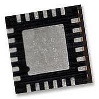
IMU-3000 INVENSENSE, IMU-3000 Datasheet - Page 21

IMU-3000
Manufacturer Part Number
IMU-3000
Description
GYRO, TRI-AXIS, PROG +/-2000 DEG/S
Manufacturer
INVENSENSE
Datasheet
1.IMU-3000.pdf
(56 pages)
Specifications of IMU-3000
No. Of Axes
3
Sensor Case Style
QFN
No. Of Pins
24
Supply Voltage Range
2.1V To 3.6V
Operating Temperature Range
-40°C To +85°C
Interface
I2C, Serial
Interface Type
I2C, Serial
Rohs Compliant
Yes
Lead Free Status / RoHS Status
Lead free / RoHS Compliant
7
7.1
The internal registers of the IMU-3000 can be accessed using I
Serial Interface
7.1.1
I
lines are open-drain and bi-directional. In a generalized I
be a master or a slave. The master device puts the slave address on the bus, and the slave device with the
matching address acknowledges the master.
The IMU-3000 always operates as a slave device when communicating to the system processor, which thus
acts as the master. SDA and SCL lines typically need pull-up resistors to VDD. The maximum bus speed is
400kHz.
The slave address of the IMU-3000 is b110100X which is 7 bits long. The LSB bit of the 7 bit address is
determined by the logic level on pin ADO. This allows two IMU-3000s to be connected to the same I
When used in this configuration, the address of the one of the devices should be b1101000 (pin ADO is logic
low) and the address of the other should be b1101001 (pin AD0 is logic high). The I
the WHO_AM_I register.
I
START (S) and STOP (P) Conditions
Communication on the I
defined as a HIGH-to-LOW transition of the SDA line while SCL line is HIGH (see figure below). The bus is
considered to be busy until the master puts a STOP condition (P) on the bus, which is defined as a LOW to
HIGH transition on the SDA line while SCL is HIGH (see figure below).
Additionally, the bus remains busy if a repeated START (Sr) is generated instead of a STOP condition.
2
2
C is a two-wire interface comprised of the signals serial data (SDA) and serial clock (SCL). In general, the
C Communications Protocol
Digital Interface
I
2
I
C Serial Interface
2
C Interface
Number
Pin
23
24
8
9
Pin Name
VLOGIC
AD0
SCL
SDA
2
C bus starts when the master puts the START condition (S) on the bus, which is
IMU-3000 Product Specification
START and STOP Conditions
Pin Description
Digital I/O supply voltage. VLOGIC must be ≤ VDD at
all times.
I
I
I
2
2
2
C Slave Address LSB
C serial clock
C serial data
21 of 56
2
C interface implementation, attached devices can
2
C at up to 400kHz.
Document Number: PS-IMU-3000A-00-01.1
Revision: 1.1
Release Date: 08/19/2010
2
C address is stored in
2
C bus.


