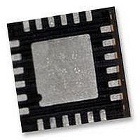
IMU-3000 INVENSENSE, IMU-3000 Datasheet - Page 31

IMU-3000
Manufacturer Part Number
IMU-3000
Description
GYRO, TRI-AXIS, PROG +/-2000 DEG/S
Manufacturer
INVENSENSE
Datasheet
1.IMU-3000.pdf
(56 pages)
Specifications of IMU-3000
No. Of Axes
3
Sensor Case Style
QFN
No. Of Pins
24
Supply Voltage Range
2.1V To 3.6V
Operating Temperature Range
-40°C To +85°C
Interface
I2C, Serial
Interface Type
I2C, Serial
Rohs Compliant
Yes
Lead Free Status / RoHS Status
Lead free / RoHS Compliant
10.3 Register 18 – FIFO Enable
10.4 Registers 19 – AUX (Accel) VDDIO
Type: Read/Write
Description:
This register determines what data goes into the IMU-3000 FIFO, which is a 512 byte First-In-First-
Out buffer (see register 60). Sensor data is automatically placed into the FIFO after each ADC
sampling period is complete. The ADC sample rate is controlled by register 21.
The order at which the data is put into the FIFO is from MSB to LSB, which means that it will match
the order shown in the parameter detail below. Two bytes are used for each reading. For example,
if Gyro X, Gyro Y, Gyro Z, and FIFO_FOOTER are configured to go into the FIFO, then each sample
period the following 8 bytes would be inserted into the FIFO, as shown below:
Parameters:
TEMP_OUT
GYRO_XOUT
GYRO_YOUT
GYRO_ZOUT
AUX_XOUT
AUX_YOUT
AUX_ZOUT
FIFO_FOOTER
Type: Read/Write
Description:
This register determines the I/O logic levels for the secondary I
AUX_DA). 1=VDD, 0=VLOGIC.
Parameters:
AUX_VDDIO
0
High byte
Register
Gyro X
Register
(Hex)
(Hex)
12
13
(Decimal)
(Decimal)
Register
Register
Low byte
Gyro X
18
19
IMU-3000 Product Specification
TEMP_
Setting this inserts the Temperature reading into FIFO
Setting this inserts the X Gyro reading into FIFO
Setting this inserts the Y Gyro reading into FIFO
Setting this inserts the Z Gyro reading into FIFO
Setting this inserts the X Accelerometer reading into FIFO
Setting this inserts the Y Accelerometer reading into FIFO
Setting this inserts the Z Accelerometer reading into FIFO
Last word (2 bytes) for FIFO read. Described in more detail in Section 60
I/O logic levels for the secondary I
AUX_DA). 1=VDD, 0=VLOGIC.
Load zeros into Bits 0, 1, 3-7.
High byte
OUT
Bit7
Bit7
Gyro Y
0
GYRO_
XOUT
Bit6
Bit6
0
Low byte
Gyro Y
31 of 56
GYRO_
YOUT
Bit5
Bit5
0
High byte
Gyro Z
GYRO_
ZOUT
Bit4
Bit4
0
2
C bus clock and data lines (AUX_CL,
Low byte
Gyro Z
XOUT
AUX_
Bit3
Bit3
0
2
C bus clock and data lines (AUX_CL,
Document Number: PS-IMU-3000A-00-01.1
Revision: 1.1
Release Date: 08/19/2010
FIFO_FOOTER
VDDIO
YOUT
AUX_
AUX_
Bit2
Bit2
High byte
ZOUT
AUX_
Bit1
Bit1
0
FIFO_FOOTER
FOOTER
FIFO_
Low byte
Bit0
Bit0
0
Default
Default
Value
Value
00h
00h


