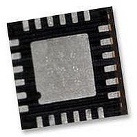
IMU-3000 INVENSENSE, IMU-3000 Datasheet - Page 23

IMU-3000
Manufacturer Part Number
IMU-3000
Description
GYRO, TRI-AXIS, PROG +/-2000 DEG/S
Manufacturer
INVENSENSE
Datasheet
1.IMU-3000.pdf
(56 pages)
Specifications of IMU-3000
No. Of Axes
3
Sensor Case Style
QFN
No. Of Pins
24
Supply Voltage Range
2.1V To 3.6V
Operating Temperature Range
-40°C To +85°C
Interface
I2C, Serial
Interface Type
I2C, Serial
Rohs Compliant
Yes
Lead Free Status / RoHS Status
Lead free / RoHS Compliant
To write the internal IMU-3000 registers, the master transmits the start condition (S), followed by the I
address and the write bit (0). At the 9
transfer. Then the master puts the register address (RA) on the bus. After the IMU-3000 acknowledges the
reception of the register address, the master puts the register data onto the bus. This is followed by the ACK
signal, and data transfer may be concluded by the stop condition (P). To write multiple bytes after the last
ACK signal, the master can continue outputting data rather than transmitting a stop signal. In this case, the
IMU-3000 automatically increments the register address and loads the data to the appropriate register. The
following figures show single and two-byte write sequences.
Single-Byte Write Sequence
Burst Write Sequence
To read the internal IMU-3000 registers, the master sends a start condition, followed by the I
a write bit, and then the register address that is going to be read. Upon receiving the ACK signal from the
IMU-3000, the master transmits a start signal followed by the slave address and read bit. As a result, the
IMU-3000 sends an ACK signal and the data. The communication ends with a not acknowledge (NACK)
signal and a stop bit from master. The NACK condition is defined such that the SDA line remains high at the
9
Single-Byte Read Sequence
Burst Read Sequence
I
2
th
C Terms
Master
Slave
Master
Slave
Master
Slave
Master
Slave
clock cycle. The following figures show single and two-byte read sequences.
Signal
NACK
DATA
ACK
AD
RA
W
R
S
P
S
S
S
S
Description
Slave I
Not-Acknowledge: SDA line stays high at the 9
IMU-3000 internal register address
Transmit or received data
Start Condition: SDA goes from high to low while SCL is high
Write bit (0)
Read bit (1)
Acknowledge: SDA line is low while the SCL line is high at the 9
Stop condition: SDA going from low to high while SCL is high
AD+W
AD+W
AD+W
AD+W
2
C address
ACK
ACK
ACK
ACK
IMU-3000 Product Specification
RA
RA
RA
RA
ACK
ACK
th
ACK
ACK
clock cycle (when the clock is high), the IMU-3000 acknowledges the
S
S
DATA
DATA
AD+R
AD+R
23 of 56
ACK
ACK
ACK
ACK
DATA
th
P
clock cycle
DATA
DATA
ACK
ACK
NACK
Document Number: PS-IMU-3000A-00-01.1
Revision: 1.1
Release Date: 08/19/2010
P
th
DATA
clock cycle
P
NACK
2
C address and
P
2
C


