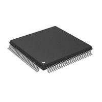
ADSP-2187LKSTZ-210 Analog Devices Inc, ADSP-2187LKSTZ-210 Datasheet - Page 15

ADSP-2187LKSTZ-210
Manufacturer Part Number
ADSP-2187LKSTZ-210
Description
IC DSP CONTRLR 16BIT 100-TQFP
Manufacturer
Analog Devices Inc
Series
ADSP-21xxr
Type
Fixed Pointr
Datasheet
1.ADSP-2184LBSTZ-160.pdf
(48 pages)
Specifications of ADSP-2187LKSTZ-210
Interface
Host Interface, Serial Port
Clock Rate
52MHz
Non-volatile Memory
External
On-chip Ram
160kB
Voltage - I/o
3.30V
Voltage - Core
3.30V
Operating Temperature
0°C ~ 70°C
Mounting Type
Surface Mount
Package / Case
100-TQFP, 100-VQFP
Device Core Size
16b
Format
Fixed Point
Clock Freq (max)
52.5MHz
Mips
52.5
Device Input Clock Speed
52.5MHz
Ram Size
160KB
Program Memory Size
Not RequiredKB
Operating Supply Voltage (typ)
3.3V
Operating Supply Voltage (min)
3V
Operating Supply Voltage (max)
3.6V
Operating Temp Range
0C to 70C
Operating Temperature Classification
Commercial
Mounting
Surface Mount
Pin Count
100
Package Type
LQFP
Lead Free Status / RoHS Status
Lead free / RoHS Compliant
Other names
ADSP-2187LKSTZ210
Designing an EZ-ICE-Compatible System
ADSP-218xL series members have on-chip emulation support
and an ICE-Port, a special set of pins that interface to the
EZ-ICE. These features allow in-circuit emulation without
replacing the target system processor by using only a 14-pin
connection from the target system to the EZ-ICE. Target sys-
tems must have a 14-pin connector to accept the EZ-ICE’s in-
circuit probe, a 14-pin plug.
Issuing the chip reset command during emulation causes the
DSP to perform a full chip reset, including a reset of its memory
mode. Therefore, it is vital that the mode pins are set correctly
PRIOR to issuing a chip reset command from the emulator user
interface. If a passive method of maintaining mode information
is being used (as discussed in
it does not matter that the mode information is latched by an
emulator reset. However, if the RESET pin is being used as a
method of setting the value of the mode pins, the effects of an
emulator reset must be taken into consideration.
One method of ensuring that the values located on the mode
pins are those desired is to construct a circuit like the one shown
in
pin to logic high, regardless of whether it is latched via the
RESET or ERESET pin.
The ICE-Port interface consists of the following ADSP-218xL
pins: EBR, EINT, EE, EBG, ECLK, ERESET, ELIN, EMS, and
ELOUT.
These ADSP-218xL pins must be connected only to the EZ-ICE
connector in the target system. These pins have no function
except during emulation, and do not require pull-up or pull-
down resistors. The traces for these signals between the
ADSP-218xL and the connector must be kept as short as possi-
ble, no longer than 3 inches.
The following pins are also used by the EZ-ICE: BR, BG, RESET,
and GND.
The EZ-ICE uses the EE (emulator enable) signal to take control
of the ADSP-218xL in the target system. This causes the proces-
sor to use its ERESET, EBR, and EBG pins instead of the RESET,
BR, and BG pins. The BG output is three-stated. These signals
do not need to be jumper-isolated in the system.
• Complete assembly and disassembly of instructions
• C source-level debugging
Figure
13. This circuit forces the value located on the Mode A
Figure 13. Mode A Pin/EZ-ICE Circuit
1k
Setting Memory Mode on Page
PROGRAMMABLE I/O
MODE A/PF0
ERESET
RESET
ADSP-218xL
ADSP-2184L/ADSP-2185L/ADSP-2186L/ADSP-2187L
Rev. C | Page 15 of 48 | January 2008
4),
The EZ-ICE connects to the target system via a ribbon cable and
a 14-pin female plug. The female plug is plugged onto the 14-
pin connector (a pin strip header) on the target board.
Target Board Connector for EZ-ICE Probe
The EZ-ICE connector (a standard pin strip header) is shown in
Figure
design to use the EZ-ICE. Be sure to allow enough room in the
system to fit the EZ-ICE probe onto the 14-pin connector.
The 14-pin, 2-row pin strip header is keyed at the Pin 7 loca-
tion—Pin 7 must be removed from the header. The pins must
be 0.025 inch square and at least 0.20 inch in length. Pin spacing
should be 0.1 0.1 inch. The pin strip header must have at least
0.15 inch clearance on all sides to accept the EZ-ICE probe plug.
Pin strip headers are available from vendors such as 3M,
McKenzie, and Samtec.
Target Memory Interface
For the target system to be compatible with the EZ-ICE emula-
tor, it must comply with the following memory interface
guidelines:
Design the Program Memory (PM), Data Memory (DM), Byte
Memory (BM), I/O Memory (IOM), and Composite Memory
(CM) external interfaces to comply with worst-case device
timing requirements and switching characteristics as specified
in this data sheet. The performance of the EZ-ICE may
approach published worst-case specification for some memory
access timing requirements and switching characteristics.
Note: If the target does not meet the worst-case chip specifica-
tion for memory access parameters, the circuitry may not be
able to be emulated at the desired CLKIN frequency. Depending
on the severity of the specification violation, the system may be
difficult to manufacture, as DSP components statistically vary in
switching characteristic and timing requirements, within pub-
lished limits.
Restriction: All memory strobe signals on the ADSP-218xL
(RD, WR, PMS, DMS, BMS, CMS, and IOMS) used in the target
system must have 10 kΩ pull-up resistors connected when the
EZ-ICE is being used. The pull-up resistors are necessary
14. This connector must be added to the target board
Figure 14. Target Board Connector for EZ-ICE
KEY (NO PIN)
ELOUT
RESET
GND
EBG
EBR
EE
11
13
1
9
3
5
7
TOP VIEW
12
10
14
2
4
6
8
ERESET
BG
BR
EINT
ELIN
ECLK
EMS


