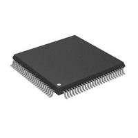
ADSP-2187LKSTZ-210 Analog Devices Inc, ADSP-2187LKSTZ-210 Datasheet - Page 45

ADSP-2187LKSTZ-210
Manufacturer Part Number
ADSP-2187LKSTZ-210
Description
IC DSP CONTRLR 16BIT 100-TQFP
Manufacturer
Analog Devices Inc
Series
ADSP-21xxr
Type
Fixed Pointr
Datasheet
1.ADSP-2184LBSTZ-160.pdf
(48 pages)
Specifications of ADSP-2187LKSTZ-210
Interface
Host Interface, Serial Port
Clock Rate
52MHz
Non-volatile Memory
External
On-chip Ram
160kB
Voltage - I/o
3.30V
Voltage - Core
3.30V
Operating Temperature
0°C ~ 70°C
Mounting Type
Surface Mount
Package / Case
100-TQFP, 100-VQFP
Device Core Size
16b
Format
Fixed Point
Clock Freq (max)
52.5MHz
Mips
52.5
Device Input Clock Speed
52.5MHz
Ram Size
160KB
Program Memory Size
Not RequiredKB
Operating Supply Voltage (typ)
3.3V
Operating Supply Voltage (min)
3V
Operating Supply Voltage (max)
3.6V
Operating Temp Range
0C to 70C
Operating Temperature Classification
Commercial
Mounting
Surface Mount
Pin Count
100
Package Type
LQFP
Lead Free Status / RoHS Status
Lead free / RoHS Compliant
Other names
ADSP-2187LKSTZ210
BGA PACKAGE PINOUT
The BGA package pinout is shown in
bold text in the table replace the plain text named functions
when Mode C equals 1. A plus sign (+) separates two functions
when either function can be active for either major I/O mode.
Signals enclosed in brackets are state bits latched from the value
Table 30. BGA Pin Assignments
1
Ball No.
A01
A02
A03
A04
A05
A06
A07
A08
A09
A10
A11
A12
B01
B02
B03
B04
B05
B06
B07
B08
B09
B10
B11
B12
C01
C02
C03
C04
C05
C06
C07
C08
C09
C10
C11
C12
Mode D function available on ADSP-2187L only.
Ball Name
A2/IAD1
A1/IAD0
GND
A0
NC
GND
NC
NC
NC
D22
GND
GND
A4/IAD3
A3/IAD2
GND
NC
NC
GND
V
D23
D20
D18
D17
D16
PWDACK
A6/IAD5
RD
A5/IAD4
A7/IAD6
PWD
V
D21
D19
D15
NC
D14
DDEXT
DDEXT
Ball No.
D01
D02
D03
D04
D05
D06
D07
D08
D09
D10
D11
D12
E01
E02
E03
E04
E05
E06
E07
E08
E09
E10
E11
E12
F01
F02
F03
F04
F05
F06
F07
F08
F09
F10
F11
F12
Table
30. Pin names in
Ball Name
NC
WR
NC
BGH
A9/IAD8
PF1 [MODE B]
PF2 [MODE C]
NC
D13
D12
NC
GND
V
V
A8/IAD7
FL0
PF0 [MODE A]
FL2
PF3 [MODE D
GND
GND
V
GND
D10
A13/IAD12
NC
A12/IAD11
A11/IAD10
FL1
NC
NC
D7/IWR
D11
D8
NC
D9
DDEXT
DDEXT
DDEXT
ADSP-2184L/ADSP-2185L/ADSP-2186L/ADSP-2187L
Rev. C | Page 45 of 48 | January 2008
1
]
Ball No.
G01
G02
G03
G04
G05
G06
G07
G08
G09
G10
G11
G12
H01
H02
H03
H04
H05
H06
H07
H08
H09
H10
H11
H12
J01
J02
J03
J04
J05
J06
J07
J08
J09
J10
J11
J12
of the pin at the deassertion of RESET. The multiplexed pins
DT1/FO, TFS1/IRQ1, RFS1/IRQ0, and DR1/FI, are mode
selectable by setting Bit 10 (SPORT1 configure) of the System
Control Register. If Bit 10 = 1, these pins have serial port func-
tionality. If Bit 10 = 0, these pins are the external interrupt and
flag pins. This bit is set to 1 by default upon reset.
Ball Name
XTAL
NC
GND
A10/IAD9
NC
NC
NC
D6/IRD
D5/IAL
NC
NC
D4/IS
CLKIN
GND
GND
GND
V
DT0
TFS0
D2/IAD15
D3/IACK
GND
NC
GND
CLKOUT
V
NC
V
V
SCLK0
D0/IAD13
RFS1/IRQ0
BG
D1/IAD14
V
V
DDINT
DDINT
DDEXT
DDEXT
DDINT
DDINT
Ball No.
K01
K02
K03
K04
K05
K06
K07
K08
K09
K10
K11
K12
L01
L02
L03
L04
L05
L06
L07
L08
L09
L10
L11
L12
M01
M02
M03
M04
M05
M06
M07
M08
M09
M10
M11
M12
Ball Name
BMS
SCLK1
IRQL1 + PF6
IOMS
PMS
EINT
NC
NC
NC
DMS
RFS0
TFS1/IRQ1
ERESET
EBR
BR
EBG
IRQE + PF4
NC
GND
DR0
GND
RESET
ELIN
ELOUT
IRQL0 + PF5
IRQL2 + PF7
NC
CMS
GND
DT1/FO
DR1/FI
GND
NC
EMS
EE
ECLK


