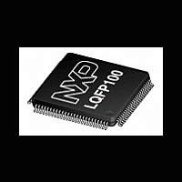
LPC2361_62 NXP Semiconductors, LPC2361_62 Datasheet - Page 10

LPC2361_62
Manufacturer Part Number
LPC2361_62
Description
The LPC2361/2362 microcontrollers are based on a 16-bit/32-bit ARM7TDMI-S CPU with real-time emulation that combines the microcontroller with up to 128 kB of embedded high-speed flash memory
Manufacturer
NXP Semiconductors
Datasheet
1.LPC2361_62.pdf
(64 pages)
NXP Semiconductors
Table 3.
LPC2361_62
Product data sheet
Symbol
P1[30]/V
P1[31]/SCK1/AD0[5] 20
P2[0] to P2[31]
P2[0]/PWM1[1]/
TXD1/TRACECLK
P2[1]/PWM1[2]/
RXD1/PIPESTAT0
P2[2]/PWM1[3]/
CTS1/PIPESTAT1
P2[3]/PWM1[4]/
DCD1/PIPESTAT2
P2[4]/PWM1[5]/
DSR1/TRACESYNC
P2[5]/PWM1[6]/
DTR1/TRACEPKT0
P2[6]/PCAP1[0]/RI1/
TRACEPKT1
BUS
Pin description
/AD0[4]
Pin
21
75
74
73
70
69
68
67
[2]
[2]
[1]
[1]
[1]
[1]
[1]
[1]
[1]
…continued
Type
I/O
I
I
I/O
I/O
I
I/O
I/O
O
O
O
I/O
O
I
O
I/O
O
I
O
I/O
O
I
O
I/O
O
I
O
I/O
O
O
O
I/O
I
I
O
Description
P1[30] — General purpose digital input/output pin.
V
Note: This signal must be HIGH for USB reset to occur.
AD0[4] — A/D converter 0, input 4.
P1[31] — General purpose digital input/output pin.
SCK1 — Serial Clock for SSP1.
AD0[5] — A/D converter 0, input 5.
Port 2: Port 2 is a 32-bit I/O port with individual direction controls for each bit. The
operation of port 2 pins depends upon the pin function selected via the pin
connect block. Pins 14 through 31 of this port are not available.
P2[0] — General purpose digital input/output pin.
PWM1[1] — Pulse Width Modulator 1, channel 1 output.
TXD1 — Transmitter output for UART1.
TRACECLK — Trace Clock.
P2[1] — General purpose digital input/output pin.
PWM1[2] — Pulse Width Modulator 1, channel 2 output.
RXD1 — Receiver input for UART1.
PIPESTAT0 — Pipeline Status, bit 0.
P2[2] — General purpose digital input/output pin.
PWM1[3] — Pulse Width Modulator 1, channel 3 output.
CTS1 — Clear to Send input for UART1.
PIPESTAT1 — Pipeline Status, bit 1.
P2[3] — General purpose digital input/output pin.
PWM1[4] — Pulse Width Modulator 1, channel 4 output.
DCD1 — Data Carrier Detect input for UART1.
PIPESTAT2 — Pipeline Status, bit 2.
P2[4] — General purpose digital input/output pin.
PWM1[5] — Pulse Width Modulator 1, channel 5 output.
DSR1 — Data Set Ready input for UART1.
TRACESYNC — Trace Synchronization.
P2[5] — General purpose digital input/output pin.
PWM1[6] — Pulse Width Modulator 1, channel 6 output.
DTR1 — Data Terminal Ready output for UART1.
TRACEPKT0 — Trace Packet, bit 0.
P2[6] — General purpose digital input/output pin.
PCAP1[0] — Capture input for PWM1, channel 0.
RI1 — Ring Indicator input for UART1.
TRACEPKT1 — Trace Packet, bit 1.
All information provided in this document is subject to legal disclaimers.
BUS
— Monitors the presence of USB bus power.
Rev. 5 — 25 October 2011
Single-chip 16-bit/32-bit MCU
LPC2361/62
© NXP B.V. 2011. All rights reserved.
10 of 64


