OM11043 NXP Semiconductors, OM11043 Datasheet - Page 27
OM11043
Manufacturer Part Number
OM11043
Description
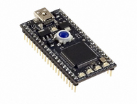
DEVELOPMENT BOARD LPC1768 MBED
Manufacturer
NXP Semiconductors
Series
mbedr
Type
MCUr
Specifications of OM11043
Contents
Board and software
Development Tool Type
Hardware / Software - Eval/Demo Board
Kit Contents
Board Cable Docs
Mcu Supported Families
LPC1000
Tool / Board Applications
General Purpose MCU, MPU, DSP, DSC
Silicon Manufacturer
NXP
Core Architecture
ARM
Core Sub-architecture
Cortex - M3
Silicon Core Number
LPC17xx
Silicon Family Name
LPC17xx
Lead Free Status / RoHS Status
Lead free / RoHS Compliant
For Use With/related Products
LPC1768
Lead Free Status / RoHS Status
Lead free / RoHS Compliant
Other names
568-4916
Available stocks
Company
Part Number
Manufacturer
Quantity
Price


NXP Semiconductors
LPC1769_68_67_66_65_64_63
Product data sheet
7.16.1 Features
7.17.1 Features
7.16 UARTs
7.17 SPI serial I/O controller
7.18 SSP serial I/O controller
The LPC17xx each contain four UARTs. In addition to standard transmit and receive data
lines, UART1 also provides a full modem control handshake interface and support for
RS-485/9-bit mode allowing both software address detection and automatic address
detection using 9-bit mode.
The UARTs include a fractional baud rate generator. Standard baud rates such as
115200 Bd can be achieved with any crystal frequency above 2 MHz.
The LPC17xx contain one SPI controller. SPI is a full duplex serial interface designed to
handle multiple masters and slaves connected to a given bus. Only a single master and a
single slave can communicate on the interface during a given data transfer. During a data
transfer the master always sends 8 bits to 16 bits of data to the slave, and the slave
always sends 8 bits to 16 bits of data to the master.
The LPC17xx contain two SSP controllers. The SSP controller is capable of operation on
a SPI, 4-wire SSI, or Microwire bus. It can interact with multiple masters and slaves on the
bus. Only a single master and a single slave can communicate on the bus during a given
•
•
•
•
•
•
•
•
•
•
•
•
•
•
•
•
Maximum UART data bit rate of 6.25 Mbit/s.
16 B Receive and Transmit FIFOs.
Register locations conform to 16C550 industry standard.
Receiver FIFO trigger points at 1 B, 4 B, 8 B, and 14 B.
Built-in fractional baud rate generator covering wide range of baud rates without a
need for external crystals of particular values.
Auto baud capabilities and FIFO control mechanism that enables software flow
control implementation.
UART1 equipped with standard modem interface signals. This module also provides
full support for hardware flow control (auto-CTS/RTS).
Support for RS-485/9-bit/EIA-485 mode (UART1).
UART3 includes an IrDA mode to support infrared communication.
All UARTs have DMA support.
Maximum SPI data bit rate of 12.5 Mbit/s
Compliant with SPI specification
Synchronous, serial, full duplex communication
Combined SPI master and slave
Maximum data bit rate of one eighth of the input clock rate
8 bits to 16 bits per transfer
All information provided in this document is subject to legal disclaimers.
Rev. 6.01 — 11 March 2011
LPC1769/68/67/66/65/64/63
32-bit ARM Cortex-M3 microcontroller
© NXP B.V. 2011. All rights reserved.
27 of 79
Related parts for OM11043
Image
Part Number
Description
Manufacturer
Datasheet
Request
R

Part Number:
Description:
NXP Semiconductors designed the LPC2420/2460 microcontroller around a 16-bit/32-bitARM7TDMI-S CPU core with real-time debug interfaces that include both JTAG andembedded trace
Manufacturer:
NXP Semiconductors
Datasheet:

Part Number:
Description:
NXP Semiconductors designed the LPC2458 microcontroller around a 16-bit/32-bitARM7TDMI-S CPU core with real-time debug interfaces that include both JTAG andembedded trace
Manufacturer:
NXP Semiconductors
Datasheet:
Part Number:
Description:
NXP Semiconductors designed the LPC2468 microcontroller around a 16-bit/32-bitARM7TDMI-S CPU core with real-time debug interfaces that include both JTAG andembedded trace
Manufacturer:
NXP Semiconductors
Datasheet:
Part Number:
Description:
NXP Semiconductors designed the LPC2470 microcontroller, powered by theARM7TDMI-S core, to be a highly integrated microcontroller for a wide range ofapplications that require advanced communications and high quality graphic displays
Manufacturer:
NXP Semiconductors
Datasheet:
Part Number:
Description:
NXP Semiconductors designed the LPC2478 microcontroller, powered by theARM7TDMI-S core, to be a highly integrated microcontroller for a wide range ofapplications that require advanced communications and high quality graphic displays
Manufacturer:
NXP Semiconductors
Datasheet:
Part Number:
Description:
The Philips Semiconductors XA (eXtended Architecture) family of 16-bit single-chip microcontrollers is powerful enough to easily handle the requirements of high performance embedded applications, yet inexpensive enough to compete in the market for hi
Manufacturer:
NXP Semiconductors
Datasheet:
Part Number:
Description:
The XA-S3 device is a member of Philips Semiconductors? XA(eXtended Architecture) family of high performance 16-bitsingle-chip microcontrollers
Manufacturer:
NXP Semiconductors
Datasheet:

Part Number:
Description:
The NXP BlueStreak LH75401/LH75411 family consists of two low-cost 16/32-bit System-on-Chip (SoC) devices
Manufacturer:
NXP Semiconductors
Datasheet:
Part Number:
Description:
The NXP LPC3130/3131 combine an 180 MHz ARM926EJ-S CPU core, high-speed USB2
Manufacturer:
NXP Semiconductors
Datasheet:
Part Number:
Description:
The NXP LPC3141 combine a 270 MHz ARM926EJ-S CPU core, High-speed USB 2
Manufacturer:
NXP Semiconductors
Part Number:
Description:
The NXP LPC3143 combine a 270 MHz ARM926EJ-S CPU core, High-speed USB 2
Manufacturer:
NXP Semiconductors

Part Number:
Description:
The NXP LPC3152 combines an 180 MHz ARM926EJ-S CPU core, High-speed USB 2
Manufacturer:
NXP Semiconductors
Part Number:
Description:
The NXP LPC3154 combines an 180 MHz ARM926EJ-S CPU core, High-speed USB 2
Manufacturer:
NXP Semiconductors

Part Number:
Description:
Standard level N-channel enhancement mode Field-Effect Transistor (FET) in a plastic package using NXP High-Performance Automotive (HPA) TrenchMOS technology
Manufacturer:
NXP Semiconductors
Datasheet: