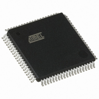
AT89C5132-ROTUL Atmel, AT89C5132-ROTUL Datasheet - Page 116

AT89C5132-ROTUL
Manufacturer Part Number
AT89C5132-ROTUL
Description
IC 8051 MCU FLASH 64K USB 80TQFP
Manufacturer
Atmel
Series
AT89C513xr
Specifications of AT89C5132-ROTUL
Core Processor
C52X2
Core Size
8-Bit
Speed
20MHz
Connectivity
IDE/ATAPI, I²C, MMC, PCM, SPI, UART/USART, USB
Peripherals
I²S, POR, WDT
Number Of I /o
44
Program Memory Size
64KB (64K x 8)
Program Memory Type
FLASH
Eeprom Size
4K x 8
Ram Size
2.25K x 8
Voltage - Supply (vcc/vdd)
2.7 V ~ 3.3 V
Data Converters
A/D 2x10b
Oscillator Type
Internal
Operating Temperature
-40°C ~ 85°C
Package / Case
80-TQFP, 80-VQFP
Cpu Family
89C
Device Core
8051
Device Core Size
8b
Frequency (max)
40MHz
Interface Type
IDE/SPI/UART/USB
Total Internal Ram Size
2.25KB
# I/os (max)
44
Number Of Timers - General Purpose
2
Operating Supply Voltage (typ)
3V
Operating Supply Voltage (max)
3.3V
Operating Supply Voltage (min)
2.7V
On-chip Adc
2-chx10-bit
Instruction Set Architecture
CISC
Operating Temp Range
-40C to 85C
Operating Temperature Classification
Industrial
Mounting
Surface Mount
Pin Count
80
Package Type
TQFP
Package
80TQFP
Family Name
89C
Maximum Speed
40 MHz
Operating Supply Voltage
3 V
Data Bus Width
8 Bit
Number Of Programmable I/os
44
Number Of Timers
2
Maximum Clock Frequency
20 MHz
Data Ram Size
2304 B
Mounting Style
SMD/SMT
A/d Bit Size
10 bit
A/d Channels Available
2
Height
1.45 mm
Length
14.1 mm
Maximum Operating Temperature
+ 85 C
Minimum Operating Temperature
- 40 C
Supply Voltage (max)
3.3 V
Supply Voltage (min)
2.7 V
Width
14.1 mm
For Use With
AT89OCD-01 - USB EMULATOR FOR AT8XC51 MCU
Lead Free Status / RoHS Status
Lead free / RoHS Compliant
Available stocks
Company
Part Number
Manufacturer
Quantity
Price
18.6.3
18.7
18.8
116
Interrupt
Registers
AT89C5132
Reset Address
On reset, the SADDR and SADEN registers are initialized to 00h, i.e. the given and broadcast
addresses are XXXX XXXXb (all don’t-care bits). This ensures that the Serial Port is backwards
compatible with the 80C51 microcontrollers that do not support automatic address recognition.
The Serial I/O Port handles two interrupt sources that are the “end of reception” (RI in SCON)
and “end of transmission” (TI in SCON) flags. As shown in Figure 18-16 these flags are com-
bined together to appear as a single interrupt source for the C51 core. Flags must be cleared by
software when executing the serial interrupt service routine.
The serial interrupt is enabled by setting ES bit in IEN0 register. This assumes interrupts are glo-
bally enabled by setting EA bit in IEN0 register.
Depending on the selected mode and whether the framing error detection is enabled or not, RI
flag is set during the stop bit or during the ninth bit as detailed in Figure 18-17.
Figure 18-16. Serial I/O Interrupt System
Figure 18-17. Interrupt Waveforms
Table 91. SCON Register
SMOD0 = X
SMOD0 = 1
SMOD0 = 0
SMOD0 = 1
SMOD0 = 1
RXD
RXD
FE
FE
RI
RI
RI
Start Bit
Start bit
SCON.0
SCON.1
RI
TI
D0
D0
D1
D1
b. Mode 2 and 3
D2
D2
IEN0.4
a. Mode 1
ES
D3
D3
8-bit Data
9-bit data
D4
D4
Serial I/O
Interrupt Request
D5
D5
D6
D6
D7
D7
Stop Bit
D8
4173E–USB–09/07
Stop bit


