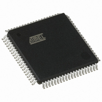
AT89C5132-ROTUL Atmel, AT89C5132-ROTUL Datasheet - Page 48

AT89C5132-ROTUL
Manufacturer Part Number
AT89C5132-ROTUL
Description
IC 8051 MCU FLASH 64K USB 80TQFP
Manufacturer
Atmel
Series
AT89C513xr
Specifications of AT89C5132-ROTUL
Core Processor
C52X2
Core Size
8-Bit
Speed
20MHz
Connectivity
IDE/ATAPI, I²C, MMC, PCM, SPI, UART/USART, USB
Peripherals
I²S, POR, WDT
Number Of I /o
44
Program Memory Size
64KB (64K x 8)
Program Memory Type
FLASH
Eeprom Size
4K x 8
Ram Size
2.25K x 8
Voltage - Supply (vcc/vdd)
2.7 V ~ 3.3 V
Data Converters
A/D 2x10b
Oscillator Type
Internal
Operating Temperature
-40°C ~ 85°C
Package / Case
80-TQFP, 80-VQFP
Cpu Family
89C
Device Core
8051
Device Core Size
8b
Frequency (max)
40MHz
Interface Type
IDE/SPI/UART/USB
Total Internal Ram Size
2.25KB
# I/os (max)
44
Number Of Timers - General Purpose
2
Operating Supply Voltage (typ)
3V
Operating Supply Voltage (max)
3.3V
Operating Supply Voltage (min)
2.7V
On-chip Adc
2-chx10-bit
Instruction Set Architecture
CISC
Operating Temp Range
-40C to 85C
Operating Temperature Classification
Industrial
Mounting
Surface Mount
Pin Count
80
Package Type
TQFP
Package
80TQFP
Family Name
89C
Maximum Speed
40 MHz
Operating Supply Voltage
3 V
Data Bus Width
8 Bit
Number Of Programmable I/os
44
Number Of Timers
2
Maximum Clock Frequency
20 MHz
Data Ram Size
2304 B
Mounting Style
SMD/SMT
A/d Bit Size
10 bit
A/d Channels Available
2
Height
1.45 mm
Length
14.1 mm
Maximum Operating Temperature
+ 85 C
Minimum Operating Temperature
- 40 C
Supply Voltage (max)
3.3 V
Supply Voltage (min)
2.7 V
Width
14.1 mm
For Use With
AT89OCD-01 - USB EMULATOR FOR AT8XC51 MCU
Lead Free Status / RoHS Status
Lead free / RoHS Compliant
Available stocks
Company
Part Number
Manufacturer
Quantity
Price
11.5
48
Registers
AT89C5132
Notes:
Table 18. PCON Register
PCON (S:87h) – Power Configuration Register
Reset Value = 00XX 0000b
Bit Number
SMOD1
–
5 - 4
7
7
6
3
2
1
0
A logic high on the RST pin clears PD bit in PCON register directly and
asynchronously. This starts the oscillator and restores the clock to the CPU and
peripherals. Program execution momentarily resumes with the instruction
immediately following the instruction that activated Power-down mode and may
continue for a number of clock cycles before the internal reset algorithm takes
control. Reset initializes the AT89C5132 and vectors the CPU to address 0000h.
1. During the time that execution resumes, the internal RAM cannot be accessed; however, it is
2. Exit from power-down by reset redefines all the SFRs, but does not affect the internal RAM
possible for the Port pins to be accessed. To avoid unexpected outputs at the Port pins, the
instruction immediately following the instruction that activated the Power-down mode should
not write to a Port pin or to the external RAM.
content.
Mnemonic
SMOD0
SMOD1
SMOD0
GF1
GF0
IDL
Bit
PD
6
-
Description
Serial Port Mode Bit 1
Set to select double baud rate in mode 1,2 or 3.
Serial Port Mode Bit 0
Set to select FE bit in SCON register.
Clear to select SM0 bit in SCON register.
Reserved
The value read from these bits is indeterminate. Do not set these bits.
General-Purpose Flag 1
One use is to indicate whether an interrupt occurred during normal operation or during
Idle mode.
General-Purpose Flag 0
One use is to indicate whether an interrupt occurred during normal operation or during
Idle mode.
Power-Down Mode Bit
Cleared by hardware when an interrupt or reset occurs.
Set to activate the Power-down mode.
If IDL and PD are both set, PD takes precedence.
Idle Mode Bit
Cleared by hardware when an interrupt or reset occurs.
Set to activate the Idle mode.
If IDL and PD are both set, PD takes precedence.
5
-
4
-
GF1
3
GF0
2
PD
1
4173E–USB–09/07
IDL
0


