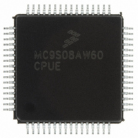
MC9S08AW60CPUE Freescale Semiconductor, MC9S08AW60CPUE Datasheet - Page 228

MC9S08AW60CPUE
Manufacturer Part Number
MC9S08AW60CPUE
Description
IC MCU 64K FLASH 64-LQFP
Manufacturer
Freescale Semiconductor
Series
HCS08r
Datasheet
1.MC9S08AW32CFDE.pdf
(324 pages)
Specifications of MC9S08AW60CPUE
Core Processor
HCS08
Core Size
8-Bit
Speed
40MHz
Connectivity
I²C, SCI, SPI
Peripherals
LVD, POR, PWM, WDT
Number Of I /o
54
Program Memory Size
60KB (60K x 8)
Program Memory Type
FLASH
Ram Size
2K x 8
Voltage - Supply (vcc/vdd)
2.7 V ~ 5.5 V
Data Converters
A/D 16x10b
Oscillator Type
Internal
Operating Temperature
-40°C ~ 85°C
Package / Case
64-LQFP
Processor Series
S08AW
Core
HCS08
Data Bus Width
8 bit
Data Ram Size
2 KB
Interface Type
SCI/SPI
Maximum Clock Frequency
40 MHz
Number Of Programmable I/os
54
Number Of Timers
8
Operating Supply Voltage
- 0.3 V to + 5.8 V
Maximum Operating Temperature
+ 85 C
Mounting Style
SMD/SMT
3rd Party Development Tools
EWS08
Development Tools By Supplier
DEMO9S08AW60E
Minimum Operating Temperature
- 40 C
On-chip Adc
16-ch x 10-bit
For Use With
DEMO9S08AW60E - DEMO BOARD FOR MC9S08AW60
Lead Free Status / RoHS Status
Lead free / RoHS Compliant
Eeprom Size
-
Lead Free Status / Rohs Status
Lead free / RoHS Compliant
Available stocks
Company
Part Number
Manufacturer
Quantity
Price
Company:
Part Number:
MC9S08AW60CPUE
Manufacturer:
TDK-LAMBDA
Quantity:
92
Company:
Part Number:
MC9S08AW60CPUE
Manufacturer:
FREESCALE
Quantity:
4 000
Company:
Part Number:
MC9S08AW60CPUE
Manufacturer:
Freescale Semiconductor
Quantity:
10 000
Part Number:
MC9S08AW60CPUE
Manufacturer:
FREESCALE
Quantity:
20 000
Company:
Part Number:
MC9S08AW60CPUER
Manufacturer:
Freescale Semiconductor
Quantity:
10 000
- Current page: 228 of 324
- Download datasheet (4Mb)
Chapter 13 Inter-Integrated Circuit (S08IICV1)
13.4.1.8
The clock synchronization mechanism can be used as a handshake in data transfer. Slave devices may hold
the SCL low after completion of one byte transfer (9 bits). In such case, it halts the bus clock and forces
the master clock into wait states until the slave releases the SCL line.
13.4.1.9
The clock synchronization mechanism can be used by slaves to slow down the bit rate of a transfer. After
the master has driven SCL low the slave can drive SCL low for the required period and then release it. If
the slave SCL low period is greater than the master SCL low period then the resulting SCL bus signal low
period is stretched.
13.5
The IIC is disabled after reset. The IIC cannot cause an MCU reset.
13.6
The IIC generates a single interrupt.
An interrupt from the IIC is generated when any of the events in
is set. The interrupt is driven by bit IICIF (of the IIC status register) and masked with bit IICIE (of the IIC
control register). The IICIF bit must be cleared by software by writing a one to it in the interrupt routine.
The user can determine the interrupt type by reading the status register.
228
Resets
Interrupts
SCL1
SCL2
SCL
Handshaking
Clock Stretching
Match of received calling address
Complete 1-byte transfer
Interrupt Source
INTERNAL COUNTER RESET
Arbitration Lost
Figure 13-9. IIC Clock Synchronization
Table 13-7. Interrupt Summary
MC9S08AW60 Data Sheet, Rev 2
DELAY
Status
ARBL
IAAS
TCF
Table 13-7
IICIF
IICIF
IICIF
Flag
START COUNTING HIGH PERIOD
Local Enable
occur provided the IICIE bit
IICIE
IICIE
IICIE
Freescale Semiconductor
Related parts for MC9S08AW60CPUE
Image
Part Number
Description
Manufacturer
Datasheet
Request
R
Part Number:
Description:
Manufacturer:
Freescale Semiconductor, Inc
Datasheet:
Part Number:
Description:
Manufacturer:
Freescale Semiconductor, Inc
Datasheet:
Part Number:
Description:
Manufacturer:
Freescale Semiconductor, Inc
Datasheet:
Part Number:
Description:
Manufacturer:
Freescale Semiconductor, Inc
Datasheet:
Part Number:
Description:
Manufacturer:
Freescale Semiconductor, Inc
Datasheet:
Part Number:
Description:
Manufacturer:
Freescale Semiconductor, Inc
Datasheet:
Part Number:
Description:
Manufacturer:
Freescale Semiconductor, Inc
Datasheet:
Part Number:
Description:
Manufacturer:
Freescale Semiconductor, Inc
Datasheet:
Part Number:
Description:
Manufacturer:
Freescale Semiconductor, Inc
Datasheet:
Part Number:
Description:
Manufacturer:
Freescale Semiconductor, Inc
Datasheet:
Part Number:
Description:
Manufacturer:
Freescale Semiconductor, Inc
Datasheet:
Part Number:
Description:
Manufacturer:
Freescale Semiconductor, Inc
Datasheet:
Part Number:
Description:
Manufacturer:
Freescale Semiconductor, Inc
Datasheet:
Part Number:
Description:
Manufacturer:
Freescale Semiconductor, Inc
Datasheet:
Part Number:
Description:
Manufacturer:
Freescale Semiconductor, Inc
Datasheet:


