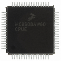
MC9S08AW60CPUE Freescale Semiconductor, MC9S08AW60CPUE Datasheet - Page 9

MC9S08AW60CPUE
Manufacturer Part Number
MC9S08AW60CPUE
Description
IC MCU 64K FLASH 64-LQFP
Manufacturer
Freescale Semiconductor
Series
HCS08r
Datasheet
1.MC9S08AW32CFDE.pdf
(324 pages)
Specifications of MC9S08AW60CPUE
Core Processor
HCS08
Core Size
8-Bit
Speed
40MHz
Connectivity
I²C, SCI, SPI
Peripherals
LVD, POR, PWM, WDT
Number Of I /o
54
Program Memory Size
60KB (60K x 8)
Program Memory Type
FLASH
Ram Size
2K x 8
Voltage - Supply (vcc/vdd)
2.7 V ~ 5.5 V
Data Converters
A/D 16x10b
Oscillator Type
Internal
Operating Temperature
-40°C ~ 85°C
Package / Case
64-LQFP
Processor Series
S08AW
Core
HCS08
Data Bus Width
8 bit
Data Ram Size
2 KB
Interface Type
SCI/SPI
Maximum Clock Frequency
40 MHz
Number Of Programmable I/os
54
Number Of Timers
8
Operating Supply Voltage
- 0.3 V to + 5.8 V
Maximum Operating Temperature
+ 85 C
Mounting Style
SMD/SMT
3rd Party Development Tools
EWS08
Development Tools By Supplier
DEMO9S08AW60E
Minimum Operating Temperature
- 40 C
On-chip Adc
16-ch x 10-bit
For Use With
DEMO9S08AW60E - DEMO BOARD FOR MC9S08AW60
Lead Free Status / RoHS Status
Lead free / RoHS Compliant
Eeprom Size
-
Lead Free Status / Rohs Status
Lead free / RoHS Compliant
Available stocks
Company
Part Number
Manufacturer
Quantity
Price
Company:
Part Number:
MC9S08AW60CPUE
Manufacturer:
TDK-LAMBDA
Quantity:
92
Company:
Part Number:
MC9S08AW60CPUE
Manufacturer:
FREESCALE
Quantity:
4 000
Company:
Part Number:
MC9S08AW60CPUE
Manufacturer:
Freescale Semiconductor
Quantity:
10 000
Part Number:
MC9S08AW60CPUE
Manufacturer:
FREESCALE
Quantity:
20 000
Company:
Part Number:
MC9S08AW60CPUER
Manufacturer:
Freescale Semiconductor
Quantity:
10 000
Section Number
1.1
1.2
1.3
2.1
2.2
2.3
3.1
3.2
3.3
3.4
3.5
3.6
4.1
4.2
4.3
Freescale Semiconductor
Overview .........................................................................................................................................19
MCU Block Diagrams .....................................................................................................................19
System Clock Distribution ..............................................................................................................21
Introduction .....................................................................................................................................23
Device Pin Assignment ...................................................................................................................24
Recommended System Connections ...............................................................................................26
Introduction .....................................................................................................................................33
Features ...........................................................................................................................................33
Run Mode ........................................................................................................................................33
Active Background Mode ................................................................................................................33
Wait Mode .......................................................................................................................................34
Stop Modes ......................................................................................................................................34
MC9S08AW60 Series Memory Map ..............................................................................................39
Register Addresses and Bit Assignments ........................................................................................43
RAM ................................................................................................................................................49
2.3.1
2.3.2
2.3.3
2.3.4
2.3.5
2.3.6
2.3.7
3.6.1
3.6.2
3.6.3
3.6.4
3.6.5
4.1.1
Power (V
Oscillator (XTAL, EXTAL) ............................................................................................28
RESET Pin ......................................................................................................................29
Background/Mode Select (BKGD/MS) .........................................................................29
ADC Reference Pins (V
External Interrupt Pin (IRQ) ...........................................................................................29
General-Purpose I/O and Peripheral Ports .....................................................................30
Stop2 Mode ....................................................................................................................35
Stop3 Mode ....................................................................................................................36
Active BDM Enabled in Stop Mode ...............................................................................36
LVD Enabled in Stop Mode ...........................................................................................37
On-Chip Peripheral Modules in Stop Modes .................................................................37
Reset and Interrupt Vector Assignments ........................................................................42
DD
, 2 x V
SS
Pins and Connections
, V
MC9S08AW60 Data Sheet, Rev 2
Modes of Operation
REFH
DDAD
Introduction
Contents
Chapter 1
Chapter 2
Chapter 3
Chapter 4
, V
, V
Memory
REFL
Title
SSAD
) ...........................................................................29
) .........................................................................28
Page
9


