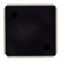
D6417729RHF200BV Renesas Electronics America, D6417729RHF200BV Datasheet - Page 241

D6417729RHF200BV
Manufacturer Part Number
D6417729RHF200BV
Description
IC SUPER H MPU ROMLESS 208QFP
Manufacturer
Renesas Electronics America
Series
SuperH® SH7700r
Datasheet
1.D6417729RF133BV.pdf
(857 pages)
Specifications of D6417729RHF200BV
Core Processor
SH-3 DSP
Core Size
32-Bit
Speed
200MHz
Connectivity
EBI/EMI, FIFO, IrDA, SCI, SmartCard
Peripherals
DMA, POR, WDT
Number Of I /o
96
Program Memory Type
ROMless
Ram Size
32K x 8
Voltage - Supply (vcc/vdd)
1.85 V ~ 2.15 V
Data Converters
A/D 8x10b; D/A 2x8b
Oscillator Type
Internal
Operating Temperature
-20°C ~ 75°C
Package / Case
208-QFP Exposed Pad, 208-eQFP, 208-HQFP
Lead Free Status / RoHS Status
Lead free / RoHS Compliant
Eeprom Size
-
Program Memory Size
-
Available stocks
Company
Part Number
Manufacturer
Quantity
Price
Company:
Part Number:
D6417729RHF200BV
Manufacturer:
EVERLIGHT
Quantity:
1 000
Company:
Part Number:
D6417729RHF200BV
Manufacturer:
Renesas Electronics America
Quantity:
10 000
- Current page: 241 of 857
- Download datasheet (5Mb)
8.1
The user break controller (UBC) provides functions that simplify program debugging. Break
conditions are set in the UBC and a user break is generated according to the conditions of the bus
cycle generated by the CPU or on-chip DMAC. The breakpoint check function monitors
instruction fetches and operand read/writes, generating a variable combination of pre-execution
instruction fetch, post-execution instruction fetch, and post-execution operand access breakpoint
traps under designated read/write conditions.
This function makes it easy to design an effective self-monitoring debugger, enabling the chip to
debug programs without using an in-circuit emulator.
8.1.1
The UBC has the following features:
The following break comparison conditions can be set.
Number of break channels: two channels (channels A and B)
User break can be requested as either the independent or sequential condition on channels A
and B (sequential break setting: when a channel A break condition match is followed by a
channel B break condition match, and both matches do not occur in the same bus cycle).
User break is generated upon satisfying break conditions. A user-designed user-break
condition exception handling routine can be run.
In an instruction fetch cycle, break setting before or after instruction execution can be set.
Breaks can be specified for on-chip I/O accesses or LDTLB instruction execution in ASE
mode.
Address (Compares 40 bits comprising a 32-bit logical address prefixed with an ASID
address. Comparison bits are maskable in 32-bit units; user can mask addresses at lower 12
bits (4-k page), lower 10 bits (1-k page), or any size of page, etc.)
One of four address buses (logic address bus (LAB), internal address bus (IAB),
X-memory address bus (XAB), or Y-memory address bus (YAB)) can be selected.
Data (only on channel B, 32-bit maskable)
One of the four data buses (logic data bus (LDB), internal data bus (IDB), X-memory data
bus (XDB), or Y-memory data bus (YDB)) can be selected.
Bus master: CPU or DMAC cycle
Bus cycle: Instruction fetch or data access
Read/write
Operand size: Byte, word, or longword
Overview
Features
Section 8 User Break Controller
Rev. 5.0, 09/03, page 193 of 806
Related parts for D6417729RHF200BV
Image
Part Number
Description
Manufacturer
Datasheet
Request
R

Part Number:
Description:
KIT STARTER FOR M16C/29
Manufacturer:
Renesas Electronics America
Datasheet:

Part Number:
Description:
KIT STARTER FOR R8C/2D
Manufacturer:
Renesas Electronics America
Datasheet:

Part Number:
Description:
R0K33062P STARTER KIT
Manufacturer:
Renesas Electronics America
Datasheet:

Part Number:
Description:
KIT STARTER FOR R8C/23 E8A
Manufacturer:
Renesas Electronics America
Datasheet:

Part Number:
Description:
KIT STARTER FOR R8C/25
Manufacturer:
Renesas Electronics America
Datasheet:

Part Number:
Description:
KIT STARTER H8S2456 SHARPE DSPLY
Manufacturer:
Renesas Electronics America
Datasheet:

Part Number:
Description:
KIT STARTER FOR R8C38C
Manufacturer:
Renesas Electronics America
Datasheet:

Part Number:
Description:
KIT STARTER FOR R8C35C
Manufacturer:
Renesas Electronics America
Datasheet:

Part Number:
Description:
KIT STARTER FOR R8CL3AC+LCD APPS
Manufacturer:
Renesas Electronics America
Datasheet:

Part Number:
Description:
KIT STARTER FOR RX610
Manufacturer:
Renesas Electronics America
Datasheet:

Part Number:
Description:
KIT STARTER FOR R32C/118
Manufacturer:
Renesas Electronics America
Datasheet:

Part Number:
Description:
KIT DEV RSK-R8C/26-29
Manufacturer:
Renesas Electronics America
Datasheet:

Part Number:
Description:
KIT STARTER FOR SH7124
Manufacturer:
Renesas Electronics America
Datasheet:

Part Number:
Description:
KIT STARTER FOR H8SX/1622
Manufacturer:
Renesas Electronics America
Datasheet:

Part Number:
Description:
KIT DEV FOR SH7203
Manufacturer:
Renesas Electronics America
Datasheet:


