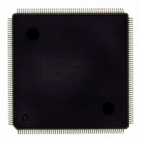
D6417729RHF200BV Renesas Electronics America, D6417729RHF200BV Datasheet - Page 455

D6417729RHF200BV
Manufacturer Part Number
D6417729RHF200BV
Description
IC SUPER H MPU ROMLESS 208QFP
Manufacturer
Renesas Electronics America
Series
SuperH® SH7700r
Datasheet
1.D6417729RF133BV.pdf
(857 pages)
Specifications of D6417729RHF200BV
Core Processor
SH-3 DSP
Core Size
32-Bit
Speed
200MHz
Connectivity
EBI/EMI, FIFO, IrDA, SCI, SmartCard
Peripherals
DMA, POR, WDT
Number Of I /o
96
Program Memory Type
ROMless
Ram Size
32K x 8
Voltage - Supply (vcc/vdd)
1.85 V ~ 2.15 V
Data Converters
A/D 8x10b; D/A 2x8b
Oscillator Type
Internal
Operating Temperature
-20°C ~ 75°C
Package / Case
208-QFP Exposed Pad, 208-eQFP, 208-HQFP
Lead Free Status / RoHS Status
Lead free / RoHS Compliant
Eeprom Size
-
Program Memory Size
-
Available stocks
Company
Part Number
Manufacturer
Quantity
Price
Company:
Part Number:
D6417729RHF200BV
Manufacturer:
EVERLIGHT
Quantity:
1 000
Company:
Part Number:
D6417729RHF200BV
Manufacturer:
Renesas Electronics America
Quantity:
10 000
- Current page: 455 of 857
- Download datasheet (5Mb)
12.3.5
Number of Bus Cycle States: When the DMAC is the bus master, the number of bus cycle states
is controlled by the bus state controller (BSC) in the same way as when the CPU is the bus master.
For details, see section 11, Bus State Controller (BSC).
D D D D R R R R E E E E Q Q Q Q Pin Sampling Timing: In external request mode, the DREQ pin is sampled by clock pulse
(CKIO) falling edge or low level detection. When DREQ input is detected, a DMAC bus cycle is
generated and DMA transfer performed, at the earliest, three states later.
The second and subsequent DREQ sampling operations are started two cycles after the first
sample.
Operation
Cycle-Steal Mode
In cycle-steal mode, the DREQ sampling timing is the same regardless of whether level or
edge detection is used.
For example, in figure 12.17 (cycle-steal mode, level input), DMAC transfer begins, at the
earliest, three cycles after the first sampling is performed. The second sampling is started two
cycles after the first. If DREQ is not detected at this time, sampling is performed in each
subsequent cycle.
Thus, DREQ sampling is performed one step in advance. The third sampling operation is not
performed until the idle cycle following the end of the first DMA transfer.
The above conditions are the same whatever the number of CPU transfer cycles, as shown in
figure 12.18. The above conditions are also the same whatever the number of DMA transfer
cycles, as shown in figure 12.19.
DACK is output in a read in the example in figure 12.17, and in a write in the example in
figure 12.18. In both cases, DACK is output for the same duration as CSn.
Figure 12.20 shows an example in which sampling is executed in all subsequent cycles when
DREQ cannot be detected.
Figure 12.21 shows examples of edge detection in the cycle-steal mode.
Number of Bus Cycle States and D D D D R R R R E E E E Q Q Q Q Pin Sampling Timing
Rev. 5.0, 09/03, page 407 of 806
Related parts for D6417729RHF200BV
Image
Part Number
Description
Manufacturer
Datasheet
Request
R

Part Number:
Description:
KIT STARTER FOR M16C/29
Manufacturer:
Renesas Electronics America
Datasheet:

Part Number:
Description:
KIT STARTER FOR R8C/2D
Manufacturer:
Renesas Electronics America
Datasheet:

Part Number:
Description:
R0K33062P STARTER KIT
Manufacturer:
Renesas Electronics America
Datasheet:

Part Number:
Description:
KIT STARTER FOR R8C/23 E8A
Manufacturer:
Renesas Electronics America
Datasheet:

Part Number:
Description:
KIT STARTER FOR R8C/25
Manufacturer:
Renesas Electronics America
Datasheet:

Part Number:
Description:
KIT STARTER H8S2456 SHARPE DSPLY
Manufacturer:
Renesas Electronics America
Datasheet:

Part Number:
Description:
KIT STARTER FOR R8C38C
Manufacturer:
Renesas Electronics America
Datasheet:

Part Number:
Description:
KIT STARTER FOR R8C35C
Manufacturer:
Renesas Electronics America
Datasheet:

Part Number:
Description:
KIT STARTER FOR R8CL3AC+LCD APPS
Manufacturer:
Renesas Electronics America
Datasheet:

Part Number:
Description:
KIT STARTER FOR RX610
Manufacturer:
Renesas Electronics America
Datasheet:

Part Number:
Description:
KIT STARTER FOR R32C/118
Manufacturer:
Renesas Electronics America
Datasheet:

Part Number:
Description:
KIT DEV RSK-R8C/26-29
Manufacturer:
Renesas Electronics America
Datasheet:

Part Number:
Description:
KIT STARTER FOR SH7124
Manufacturer:
Renesas Electronics America
Datasheet:

Part Number:
Description:
KIT STARTER FOR H8SX/1622
Manufacturer:
Renesas Electronics America
Datasheet:

Part Number:
Description:
KIT DEV FOR SH7203
Manufacturer:
Renesas Electronics America
Datasheet:


