HD64F36077GHV Renesas Electronics America, HD64F36077GHV Datasheet - Page 20
HD64F36077GHV
Manufacturer Part Number
HD64F36077GHV
Description
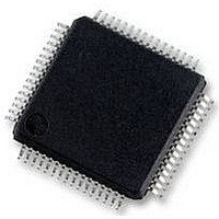
16BIT MCU FLASH 56K, SMD, LQFP64
Manufacturer
Renesas Electronics America
Datasheet
1.HD64F36077GHV.pdf
(524 pages)
Specifications of HD64F36077GHV
No. Of I/o's
47
Ram Memory Size
4KB
Cpu Speed
20MHz
No. Of Timers
4
Digital Ic Case Style
LQFP
Supply Voltage Range
4.5V
Core Size
16bit
Program Memory Size
56KB
Oscillator Type
External Only
Controller Family/series
H8/300H
Peripherals
ADC
Rohs Compliant
Yes
Lead Free Status / RoHS Status
Lead free / RoHS Compliant
Available stocks
Company
Part Number
Manufacturer
Quantity
Price
Company:

Part Number:
HD64F36077GHV
Manufacturer:
RENESAS
Quantity:
340
Part Number:
HD64F36077GHV
Manufacturer:
RENESAS/瑞萨
Quantity:
20 000


Figure 5.5 Flowchart of Clock Switching with Backup Function Disabled (2)
(From External Clock to On-Chip Oscillator Clock)................................................... 78
Figure 5.6 Timing Chart of Switching from On-Chip Oscillator Clock to External Clock .......... 79
Figure 5.7 Timing Chart to Switch from External Clock to On-Chip Oscillator Clock ............... 80
Figure 5.8 External Oscillation Backup Timing ........................................................................... 81
Figure 5.9 Example of Trimming Flow for On-Chip Oscillator Clock ........................................ 82
Figure 5.10 Timing Chart of Trimming of On-Chip Oscillator Frequency .................................. 83
Figure 5.11 Example of Connection to Crystal Resonator ........................................................... 84
Figure 5.12 Equivalent Circuit of Crystal Resonator.................................................................... 84
Figure 5.13 Example of Connection to Ceramic Resonator ......................................................... 84
Figure 5.14 Example of External Clock Input .............................................................................. 85
Figure 5.15 Block Diagram of Subclock Oscillator...................................................................... 85
Figure 5.16 Typical Connection to 32.768-kHz Crystal Resonator.............................................. 86
Figure 5.17 Equivalent Circuit of 32.768-kHz Crystal Resonator................................................ 86
Figure 5.18 Pin Connection when not Using Subclock ................................................................ 86
Figure 5.19 Example of Incorrect Board Design .......................................................................... 88
Section 6 Power-Down Modes
Figure 6.1 Mode Transition Diagram ........................................................................................... 96
Section 7 ROM
Figure 7.1 Flash Memory Block Configuration.......................................................................... 104
Figure 7.2 Programming/Erasing Flowchart Example in User Program Mode.......................... 112
Figure 7.3 Program/Program-Verify Flowchart ......................................................................... 114
Figure 7.4 Erase/Erase-Verify Flowchart ................................................................................... 117
Section 9 I/O Ports
Figure 9.1 Port 1 Pin Configuration............................................................................................ 123
Figure 9.2 Port 2 Pin Configuration............................................................................................ 129
Figure 9.3 Port 3 Pin Configuration............................................................................................ 133
Figure 9.4 Port 5 Pin Configuration............................................................................................ 137
Figure 9.5 Port 6 Pin Configuration............................................................................................ 143
Figure 9.6 Port 7 Pin Configuration............................................................................................ 148
Figure 9.7 Port 8 Pin Configuration............................................................................................ 151
Figure 9.8 Port B Pin Configuration........................................................................................... 153
Figure 9.9 Port C Pin Configuration........................................................................................... 157
Section 10 Realtime Clock (RTC)
Figure 10.1 Block Diagram of RTC ........................................................................................... 159
Figure 10.2 Definition of Time Expression ................................................................................ 165
Figure 10.3 Initial Setting Procedure.......................................................................................... 168
Figure 10.4 Example: Reading of Inaccurate Time Data............................................................ 169
Rev. 1.00 Sep. 16, 2005 Page xx of xxx
Related parts for HD64F36077GHV
Image
Part Number
Description
Manufacturer
Datasheet
Request
R


Part Number:
Description:
KIT STARTER FOR M16C/29
Manufacturer:
Renesas Electronics America
Datasheet:

Part Number:
Description:
KIT STARTER FOR R8C/2D
Manufacturer:
Renesas Electronics America
Datasheet:

Part Number:
Description:
R0K33062P STARTER KIT
Manufacturer:
Renesas Electronics America
Datasheet:

Part Number:
Description:
KIT STARTER FOR R8C/23 E8A
Manufacturer:
Renesas Electronics America
Datasheet:

Part Number:
Description:
KIT STARTER FOR R8C/25
Manufacturer:
Renesas Electronics America
Datasheet:

Part Number:
Description:
KIT STARTER H8S2456 SHARPE DSPLY
Manufacturer:
Renesas Electronics America
Datasheet:

Part Number:
Description:
KIT STARTER FOR R8C38C
Manufacturer:
Renesas Electronics America
Datasheet:

Part Number:
Description:
KIT STARTER FOR R8C35C
Manufacturer:
Renesas Electronics America
Datasheet:

Part Number:
Description:
KIT STARTER FOR R8CL3AC+LCD APPS
Manufacturer:
Renesas Electronics America
Datasheet:
Part Number:
Description:
KIT STARTER FOR RX610
Manufacturer:
Renesas Electronics America
Datasheet:

Part Number:
Description:
KIT STARTER FOR R32C/118
Manufacturer:
Renesas Electronics America
Datasheet:

Part Number:
Description:
KIT DEV RSK-R8C/26-29
Manufacturer:
Renesas Electronics America
Datasheet:

Part Number:
Description:
KIT STARTER FOR SH7124
Manufacturer:
Renesas Electronics America
Datasheet:

Part Number:
Description:
KIT STARTER FOR H8SX/1622
Manufacturer:
Renesas Electronics America
Datasheet: