PIC18C801-I/L Microchip Technology, PIC18C801-I/L Datasheet - Page 160
PIC18C801-I/L
Manufacturer Part Number
PIC18C801-I/L
Description
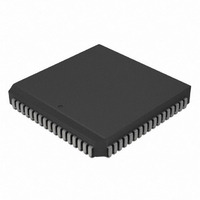
IC,MICROCONTROLLER,8-BIT,PIC CPU,CMOS,LDCC,84PIN,PLASTIC
Manufacturer
Microchip Technology
Series
PIC® 18Cr
Datasheets
1.PIC16F616T-ISL.pdf
(8 pages)
2.PIC18C601-IL.pdf
(320 pages)
3.PIC18C601-IL.pdf
(10 pages)
4.PIC18C601-IL.pdf
(10 pages)
Specifications of PIC18C801-I/L
Rohs Compliant
YES
Core Processor
PIC
Core Size
8-Bit
Speed
25MHz
Connectivity
EBI/EMI, I²C, SPI, UART/USART
Peripherals
Brown-out Detect/Reset, LVD, POR, PWM, WDT
Number Of I /o
37
Program Memory Type
ROMless
Ram Size
1.5K x 8
Voltage - Supply (vcc/vdd)
4.2 V ~ 5.5 V
Data Converters
A/D 12x10b
Oscillator Type
External
Operating Temperature
-40°C ~ 85°C
Package / Case
84-PLCC
Processor Series
PIC18C
Core
PIC
Data Bus Width
8 bit
Data Ram Size
1.5 KB
Interface Type
3-Wire, I2C, SPI, USART
Maximum Clock Frequency
25 MHz
Number Of Programmable I/os
47
Number Of Timers
1 x 16 bit
Operating Supply Voltage
2 V to 5.5 V
Maximum Operating Temperature
+ 85 C
Mounting Style
SMD/SMT
3rd Party Development Tools
52715-96, 52716-328, 52717-734, 52712-325, EWPIC18
Development Tools By Supplier
DV164005, ICE4000, DV164136
Minimum Operating Temperature
- 40 C
On-chip Adc
10 bit
Lead Free Status / RoHS Status
Lead free / RoHS Compliant
For Use With
AC164310 - MODULE SKT FOR PM3 84PLCCXLT84L1 - SOCKET TRANSITION ICE 84PLCCAC174012 - MODULE SKT PROMATEII 84PLCC
Eeprom Size
-
Program Memory Size
-
Lead Free Status / Rohs Status
Details
Other names
PIC18C801-I/LR
PIC18C801-I/LR
PIC18C801I/L
PIC18C801-I/LR
PIC18C801I/L
Available stocks
Company
Part Number
Manufacturer
Quantity
Price
Company:

Part Number:
PIC18C801-I/L
Manufacturer:
MICROCHIP
Quantity:
12 000
Company:
Part Number:
PIC18C801-I/L
Manufacturer:
Microchip Technology
Quantity:
10 000


PIC18C601/801
15.4.1.1
Once the MSSP module has been enabled, it waits for
a START condition to occur. Following the START con-
dition, the eight bits are shifted into the SSPSR register.
All incoming bits are sampled with the rising edge of the
clock (SCL) line. The value of register SSPSR<7:1> is
compared to the value of the SSPADD register. The
address is compared on the falling edge of the eighth
clock (SCL) pulse. If the addresses match, and the BF
and SSPOV bits are clear, the following events occur:
a)
b)
c)
d)
In 10-bit Address mode, two address bytes need to be
received by the slave. The five Most Significant bits
(MSb) of the first address byte, specify if this is a 10-bit
address. The R/W bit (SSPSTAT register) must specify
a write so the slave device will receive the second
address byte. For a 10-bit address, the first byte would
equal ‘1111 0 A9 A8 0’, where A9 and A8 are the
two MSb’s of the address.
The sequence of events for 10-bit addressing is as fol-
lows, with steps 7- 9 for slave-transmitter:
1.
2.
3.
4.
5.
6.
7.
8.
9.
DS39541A-page 160
The SSPSR register value is loaded into the
SSPBUF register.
The buffer full bit BF is set.
An ACK pulse is generated.
MSSP interrupt flag bit SSPIF (PIR registers) is
set on the falling edge of the ninth SCL pulse
(interrupt is generated, if enabled).
Receive first (high) byte of address (the SSPIF,
BF and UA bits (SSPSTAT register) are set).
Update the SSPADD register with second (low)
byte of address (clears bit UA and releases the
SCL line).
Read the SSPBUF register (clears bit BF) and
clear flag bit SSPIF.
Receive second (low) byte of address (bits
SSPIF, BF, and UA are set).
Update the SSPADD register with the first (high)
byte of address. If match releases SCL line, this
will clear bit UA.
Read the SSPBUF register (clears bit BF) and
clear flag bit SSPIF.
Receive repeated START condition.
Receive first (high) byte of address (bits SSPIF
and BF are set).
Read the SSPBUF register (clears bit BF) and
clear flag bit SSPIF.
Addressing
Advance Information
15.4.1.2
When the R/W bit of the address byte is clear and an
address match occurs, the R/W bit of the SSPSTAT
register is cleared. The received address is loaded into
the SSPBUF register.
When the address byte overflow condition exists, then
no acknowledge (ACK) pulse is given. An overflow con-
dition is defined as either bit BF (SSPSTAT register) is
set or bit SSPOV (SSPCON1 register) is set.
An MSSP interrupt is generated for each data transfer
byte. Flag bit SSPIF (PIR registers) must be cleared in
software. The SSPSTAT register is used to determine
the status of the byte.
15.4.1.3
When the R/W bit of the incoming address byte is set
and an address match occurs, the R/W bit of the
SSPSTAT register is set. The received address is
loaded into the SSPBUF register. The ACK pulse will
be sent on the ninth bit and pin RC3/SCK/SCL is held
low. The transmit data must be loaded into the
SSPBUF register, which also loads the SSPSR regis-
ter. Then pin RC3/SCK/SCL should be enabled by set-
ting bit CKP (SSPCON1 register). The master must
monitor the SCL pin prior to asserting another clock
pulse. The slave devices may be holding off the master
by stretching the clock. The eight data bits are shifted
out on the falling edge of the SCL input. This ensures
that the SDA signal is valid during the SCL high time
(Figure 15-8).
An MSSP interrupt is generated for each data transfer
byte. The SSPIF bit must be cleared in software and
the SSPSTAT register is used to determine the status
of the byte. The SSPIF bit is set on the falling edge of
the ninth clock pulse.
As a slave-transmitter, the ACK pulse from the master-
receiver is latched on the rising edge of the ninth SCL
input pulse. If the SDA line is high (not ACK), then the
data transfer is complete. When the ACK is latched by
the slave, the slave logic is reset (resets SSPSTAT reg-
ister) and the slave monitors for another occurrence of
the START bit. If the SDA line was low (ACK), the trans-
mit data must be loaded into the SSPBUF register, which
also loads the SSPSR register. Pin RC3/SCK/SCL
should be enabled by setting bit CKP.
Reception
Transmission
2001 Microchip Technology Inc.
Related parts for PIC18C801-I/L
Image
Part Number
Description
Manufacturer
Datasheet
Request
R

Part Number:
Description:
IC, 8BIT MCU, PIC18F, 40MHZ, LCC-44
Manufacturer:
Microchip Technology
Datasheet:
Part Number:
Description:
IC, 8BIT MCU, PIC18LF, 40MHZ, PLCC-64
Manufacturer:
Microchip Technology
Datasheet:
Part Number:
Description:
IC, 8BIT MCU, PIC18F, 64MHZ, TQFP-80
Manufacturer:
Microchip Technology
Datasheet:

Part Number:
Description:
MCU, MPU & DSP Development Tools CAN/LIN PICtail Plus Daughter Board
Manufacturer:
Microchip Technology
Datasheet:

Part Number:
Description:
IC, 8BIT MCU, PIC18F, 64MHZ, DIP-40
Manufacturer:
Microchip Technology
Datasheet:

Part Number:
Description:
IC, 8BIT MCU, PIC18LF, 40MHZ, PLCC-64
Manufacturer:
Microchip Technology
Datasheet:
Part Number:
Description:
IC, 8BIT MCU, PIC18F, 64MHZ, TQFP-64
Manufacturer:
Microchip Technology
Part Number:
Description:
IC, 8BIT MCU, PIC18F, 64MHZ, TQFP-80
Manufacturer:
Microchip Technology

Part Number:
Description:
8KB, Flash, 768bytes-RAM, 36I/O, 8-bit Family,nanowatt XLP 40 UQFN 5x5x0.5mm TUB
Manufacturer:
Microchip Technology
Datasheet:
Part Number:
Description:
8KB, Flash, 768bytes-RAM, 36I/O, 8-bit Family,nanowatt XLP 40 UQFN 5x5x0.5mm TUB
Manufacturer:
Microchip Technology
Part Number:
Description:
16KB, Flash, 768bytes-RAM, 36I/O, 8-bit Family,nanowatt XLP 40 UQFN 5x5x0.5mm TU
Manufacturer:
Microchip Technology
Datasheet:
Part Number:
Description:
16KB, Flash, 768bytes-RAM, 36I/O, 8-bit Family,nanowatt XLP 40 UQFN 5x5x0.5mm TU
Manufacturer:
Microchip Technology
Part Number:
Description:
32KB, Flash, 1536bytes-RAM, 36I/O, 8-bit Family,nanowatt XLP 40 UQFN 5x5x0.5mm T
Manufacturer:
Microchip Technology
Datasheet:
Part Number:
Description:
32KB, Flash, 1536bytes-RAM, 36I/O, 8-bit Family,nanowatt XLP 40 UQFN 5x5x0.5mm T
Manufacturer:
Microchip Technology
Part Number:
Description:
64KB, Flash, 3968bytes-RAM, 36I/O, 8-bit Family,nanowatt XLP 40 UQFN 5x5x0.5mm T
Manufacturer:
Microchip Technology
Datasheet: