PIC18C801-I/L Microchip Technology, PIC18C801-I/L Datasheet - Page 70
PIC18C801-I/L
Manufacturer Part Number
PIC18C801-I/L
Description
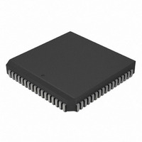
IC,MICROCONTROLLER,8-BIT,PIC CPU,CMOS,LDCC,84PIN,PLASTIC
Manufacturer
Microchip Technology
Series
PIC® 18Cr
Datasheets
1.PIC16F616T-ISL.pdf
(8 pages)
2.PIC18C601-IL.pdf
(320 pages)
3.PIC18C601-IL.pdf
(10 pages)
4.PIC18C601-IL.pdf
(10 pages)
Specifications of PIC18C801-I/L
Rohs Compliant
YES
Core Processor
PIC
Core Size
8-Bit
Speed
25MHz
Connectivity
EBI/EMI, I²C, SPI, UART/USART
Peripherals
Brown-out Detect/Reset, LVD, POR, PWM, WDT
Number Of I /o
37
Program Memory Type
ROMless
Ram Size
1.5K x 8
Voltage - Supply (vcc/vdd)
4.2 V ~ 5.5 V
Data Converters
A/D 12x10b
Oscillator Type
External
Operating Temperature
-40°C ~ 85°C
Package / Case
84-PLCC
Processor Series
PIC18C
Core
PIC
Data Bus Width
8 bit
Data Ram Size
1.5 KB
Interface Type
3-Wire, I2C, SPI, USART
Maximum Clock Frequency
25 MHz
Number Of Programmable I/os
47
Number Of Timers
1 x 16 bit
Operating Supply Voltage
2 V to 5.5 V
Maximum Operating Temperature
+ 85 C
Mounting Style
SMD/SMT
3rd Party Development Tools
52715-96, 52716-328, 52717-734, 52712-325, EWPIC18
Development Tools By Supplier
DV164005, ICE4000, DV164136
Minimum Operating Temperature
- 40 C
On-chip Adc
10 bit
Lead Free Status / RoHS Status
Lead free / RoHS Compliant
For Use With
AC164310 - MODULE SKT FOR PM3 84PLCCXLT84L1 - SOCKET TRANSITION ICE 84PLCCAC174012 - MODULE SKT PROMATEII 84PLCC
Eeprom Size
-
Program Memory Size
-
Lead Free Status / Rohs Status
Details
Other names
PIC18C801-I/LR
PIC18C801-I/LR
PIC18C801I/L
PIC18C801-I/LR
PIC18C801I/L
Available stocks
Company
Part Number
Manufacturer
Quantity
Price
Company:

Part Number:
PIC18C801-I/L
Manufacturer:
MICROCHIP
Quantity:
12 000
Company:
Part Number:
PIC18C801-I/L
Manufacturer:
Microchip Technology
Quantity:
10 000


PIC18C601/801
5.4
Chip select signals are used to select regions of exter-
nal memory and I/O devices for access. The
PIC18C801 has three chip selects and all are program-
mable. The chip select signals are CS1, CS2 and
CSIO. CS1 and CS2 are general purpose chip selects
that are used to enable large portions of program mem-
ory. CSIO is used to enable external I/O expansion.
The PIC18C601uses two of these programmable chip
selects: CS1 and CSIO.
REGISTER 5-2:
REGISTER 5-3:
DS39541A-page 70
Chip Selects
bit 7-0
bit 7-0
CSEL2 REGISTER
CSELIO REGISTER
bit 7
CSL<7:0>: Chip Select 2 Address Decode bits
XXh = All eight bits are compared to the Most Significant bits PC<20:13> of the program
00h = CS2 is inactive
Legend:
R = Readable bit
- n = Value at POR
bit7
CSIO<7:0>: Chip Select IO Address Decode bits
XXh = All eight bits are compared to the Most Significant bits PC<20:13> of the program
00h = CSIO is inactive
Legend:
R = Readable bit
- n = Value at POR
CSIO7
R/W-1
R/W-1
CSL7
counter. If PC<20:13>
counter. If PC<20:13>
If PC<20:13> < CSL<7:0>, CS2 is high.
CSIO6
R/W-1
R/W-1
CSL6
Advance Information
CSIO5
R/W-1
R/W-1
CSL5
W = Writable bit
’1’ = Bit is set
W = Writable bit
’1’ = Bit is set
CSL<7:0> register, then the CS2 signal is low.
CSIO<7:0>, then the CSIO signal is low. If not, CSIO is high.
CSIO4
R/W-1
R/W-1
CSL4
Two SFRs are used to control the chip select signals.
These are CSEL2 and CSELIO (see Register 5-2 and
Register 5-3). A chip select signal is asserted low when
the CPU makes an access to a dedicated range of
addresses specified in the chip select registers, CSEL2
and CSELIO. The 8-bit value found in either of these
registers is decoded as one of 256, 8K banks of pro-
gram memory. If both chip select registers are 00h, all
of the chip select signals are disabled and their corre-
sponding pins are configured as I/O. Since the last 512
bytes of program memory are dedicated to internal pro-
gram RAM, the chip select signals will not activate if the
program memory address falls in this range.
CSIO3
R/W-1
U = Unimplemented bit, read as ‘0’
’0’ = Bit is cleared
U = Unimplemented bit, read as ‘0’
’0’ = Bit is cleared
R/W-1
CSL3
CSIO2
R/W-1
R/W-1
CSL2
2001 Microchip Technology Inc.
x = Bit is unknown
x = Bit is unknown
CSIO1
R/W-1
R/W-1
CSL1
CSIO0
R/W-1
R/W-1
CSL0
bit 0
bit0
Related parts for PIC18C801-I/L
Image
Part Number
Description
Manufacturer
Datasheet
Request
R

Part Number:
Description:
IC, 8BIT MCU, PIC18F, 40MHZ, LCC-44
Manufacturer:
Microchip Technology
Datasheet:
Part Number:
Description:
IC, 8BIT MCU, PIC18LF, 40MHZ, PLCC-64
Manufacturer:
Microchip Technology
Datasheet:
Part Number:
Description:
IC, 8BIT MCU, PIC18F, 64MHZ, TQFP-80
Manufacturer:
Microchip Technology
Datasheet:

Part Number:
Description:
MCU, MPU & DSP Development Tools CAN/LIN PICtail Plus Daughter Board
Manufacturer:
Microchip Technology
Datasheet:

Part Number:
Description:
IC, 8BIT MCU, PIC18F, 64MHZ, DIP-40
Manufacturer:
Microchip Technology
Datasheet:

Part Number:
Description:
IC, 8BIT MCU, PIC18LF, 40MHZ, PLCC-64
Manufacturer:
Microchip Technology
Datasheet:
Part Number:
Description:
IC, 8BIT MCU, PIC18F, 64MHZ, TQFP-64
Manufacturer:
Microchip Technology
Part Number:
Description:
IC, 8BIT MCU, PIC18F, 64MHZ, TQFP-80
Manufacturer:
Microchip Technology

Part Number:
Description:
8KB, Flash, 768bytes-RAM, 36I/O, 8-bit Family,nanowatt XLP 40 UQFN 5x5x0.5mm TUB
Manufacturer:
Microchip Technology
Datasheet:
Part Number:
Description:
8KB, Flash, 768bytes-RAM, 36I/O, 8-bit Family,nanowatt XLP 40 UQFN 5x5x0.5mm TUB
Manufacturer:
Microchip Technology
Part Number:
Description:
16KB, Flash, 768bytes-RAM, 36I/O, 8-bit Family,nanowatt XLP 40 UQFN 5x5x0.5mm TU
Manufacturer:
Microchip Technology
Datasheet:
Part Number:
Description:
16KB, Flash, 768bytes-RAM, 36I/O, 8-bit Family,nanowatt XLP 40 UQFN 5x5x0.5mm TU
Manufacturer:
Microchip Technology
Part Number:
Description:
32KB, Flash, 1536bytes-RAM, 36I/O, 8-bit Family,nanowatt XLP 40 UQFN 5x5x0.5mm T
Manufacturer:
Microchip Technology
Datasheet:
Part Number:
Description:
32KB, Flash, 1536bytes-RAM, 36I/O, 8-bit Family,nanowatt XLP 40 UQFN 5x5x0.5mm T
Manufacturer:
Microchip Technology
Part Number:
Description:
64KB, Flash, 3968bytes-RAM, 36I/O, 8-bit Family,nanowatt XLP 40 UQFN 5x5x0.5mm T
Manufacturer:
Microchip Technology
Datasheet: