PIC18C801-I/L Microchip Technology, PIC18C801-I/L Datasheet - Page 207
PIC18C801-I/L
Manufacturer Part Number
PIC18C801-I/L
Description
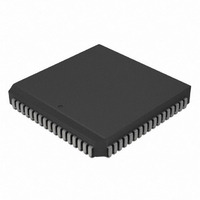
IC,MICROCONTROLLER,8-BIT,PIC CPU,CMOS,LDCC,84PIN,PLASTIC
Manufacturer
Microchip Technology
Series
PIC® 18Cr
Datasheets
1.PIC16F616T-ISL.pdf
(8 pages)
2.PIC18C601-IL.pdf
(320 pages)
3.PIC18C601-IL.pdf
(10 pages)
4.PIC18C601-IL.pdf
(10 pages)
Specifications of PIC18C801-I/L
Rohs Compliant
YES
Core Processor
PIC
Core Size
8-Bit
Speed
25MHz
Connectivity
EBI/EMI, I²C, SPI, UART/USART
Peripherals
Brown-out Detect/Reset, LVD, POR, PWM, WDT
Number Of I /o
37
Program Memory Type
ROMless
Ram Size
1.5K x 8
Voltage - Supply (vcc/vdd)
4.2 V ~ 5.5 V
Data Converters
A/D 12x10b
Oscillator Type
External
Operating Temperature
-40°C ~ 85°C
Package / Case
84-PLCC
Processor Series
PIC18C
Core
PIC
Data Bus Width
8 bit
Data Ram Size
1.5 KB
Interface Type
3-Wire, I2C, SPI, USART
Maximum Clock Frequency
25 MHz
Number Of Programmable I/os
47
Number Of Timers
1 x 16 bit
Operating Supply Voltage
2 V to 5.5 V
Maximum Operating Temperature
+ 85 C
Mounting Style
SMD/SMT
3rd Party Development Tools
52715-96, 52716-328, 52717-734, 52712-325, EWPIC18
Development Tools By Supplier
DV164005, ICE4000, DV164136
Minimum Operating Temperature
- 40 C
On-chip Adc
10 bit
Lead Free Status / RoHS Status
Lead free / RoHS Compliant
For Use With
AC164310 - MODULE SKT FOR PM3 84PLCCXLT84L1 - SOCKET TRANSITION ICE 84PLCCAC174012 - MODULE SKT PROMATEII 84PLCC
Eeprom Size
-
Program Memory Size
-
Lead Free Status / Rohs Status
Details
Other names
PIC18C801-I/LR
PIC18C801-I/LR
PIC18C801I/L
PIC18C801-I/LR
PIC18C801I/L
Available stocks
Company
Part Number
Manufacturer
Quantity
Price
Company:

Part Number:
PIC18C801-I/L
Manufacturer:
MICROCHIP
Quantity:
12 000
Company:
Part Number:
PIC18C801-I/L
Manufacturer:
Microchip Technology
Quantity:
10 000


19.0
There are several features intended to maximize
system reliability, minimize cost through elimination of
external components and provide power saving
operating modes:
• OSC Selection
• RESET
• Interrupts
• Watchdog Timer (WDT)
• SLEEP
• ID Locations
PIC18C601/801 devices have a Watchdog Timer,
which can be permanently enabled/disabled via the
configuration bits, or it can be software controlled. By
default, the Watchdog Timer is disabled to allow soft-
ware control. It runs off its own RC oscillator for cost
reduction. There are two timers that offer necessary
delays on power-up. One is the Oscillator Start-up
Timer (OST), intended to keep the chip in RESET until
the crystal oscillator is stable. The other is the Power-
up Timer (PWRT), which provides a fixed delay on
power-up only, designed to keep the part in RESET
TABLE 19-1:
Legend: x = unknown, u = unchanged, - = unimplemented, q = value depends on condition, r = reserved, maintain ‘1’.
3FFFFEh
3FFFFFh
300001h
300002h
300003h
300006h
- Power-on Reset (POR)
- Power-up Timer (PWRT)
- Oscillator Start-up Timer (OST)
2001 Microchip Technology Inc.
File Name
SPECIAL FEATURES OF THE
CPU
Shaded cells are unimplemented, read as ’0’.
CONFIG1H
CONFIG2H
CONFIG2L
CONFIG4L
DEVID1
DEVID2
CONFIGURATION BITS AND DEVICE IDs
DEV10
DEV2
Bit 7
—
—
—
r
DEV1
DEV9
Bit 6
BW
—
—
—
DEV0
DEV8
Bit 5
Advance Information
—
—
—
—
REV4
DEV7
Bit 4
—
—
—
—
WDTPS2 WDTPS1 WDTPS0
REV3
DEV6
Bit 3
—
—
—
while the power supply stabilizes. With these two tim-
ers on-chip, most applications need no external
RESET circuitry.
SLEEP mode is designed to offer a very low current
Power-down mode. The user can wake-up from
SLEEP through external RESET, Watchdog Timer
Wake-up or through an interrupt. Several oscillator
options are also available to allow the part to fit the
application. The RC oscillator option saves system
cost, while the LP crystal option saves power. By
default, HS oscillator mode is selected. There are two
main modes of operations for external memory inter-
face: 8-bit and 16-bit (default). A set of configuration
bits are used to select various options.
19.1
The configuration bits can be programmed (read as ’0’),
or left unprogrammed (read as ’1’), to select various
device configurations. These bits are mapped starting
at program memory location 300000h.
The user will note that address 300000h is beyond the
user program memory space. In fact, it belongs to the
configuration memory space (300000h - 3FFFFFh),
which can only be accessed using table reads and
table writes.
REV2
DEV5
Bit 2
—
—
—
Configuration Bits
PIC18C601/801
FOSC1
REV1
DEV4
Bit 1
—
—
PWRTEN
STVREN
WDTEN
FOSC0
REV0
DEV3
Bit 0
DS39541A-page 207
Unprogrammed
---- --11
-1-- ---1
---- 1110
1--- ---1
0000 0000
0000 0000
Default/
Value
Related parts for PIC18C801-I/L
Image
Part Number
Description
Manufacturer
Datasheet
Request
R

Part Number:
Description:
IC, 8BIT MCU, PIC18F, 40MHZ, LCC-44
Manufacturer:
Microchip Technology
Datasheet:
Part Number:
Description:
IC, 8BIT MCU, PIC18LF, 40MHZ, PLCC-64
Manufacturer:
Microchip Technology
Datasheet:
Part Number:
Description:
IC, 8BIT MCU, PIC18F, 64MHZ, TQFP-80
Manufacturer:
Microchip Technology
Datasheet:

Part Number:
Description:
MCU, MPU & DSP Development Tools CAN/LIN PICtail Plus Daughter Board
Manufacturer:
Microchip Technology
Datasheet:

Part Number:
Description:
IC, 8BIT MCU, PIC18F, 64MHZ, DIP-40
Manufacturer:
Microchip Technology
Datasheet:

Part Number:
Description:
IC, 8BIT MCU, PIC18LF, 40MHZ, PLCC-64
Manufacturer:
Microchip Technology
Datasheet:
Part Number:
Description:
IC, 8BIT MCU, PIC18F, 64MHZ, TQFP-64
Manufacturer:
Microchip Technology
Part Number:
Description:
IC, 8BIT MCU, PIC18F, 64MHZ, TQFP-80
Manufacturer:
Microchip Technology

Part Number:
Description:
8KB, Flash, 768bytes-RAM, 36I/O, 8-bit Family,nanowatt XLP 40 UQFN 5x5x0.5mm TUB
Manufacturer:
Microchip Technology
Datasheet:
Part Number:
Description:
8KB, Flash, 768bytes-RAM, 36I/O, 8-bit Family,nanowatt XLP 40 UQFN 5x5x0.5mm TUB
Manufacturer:
Microchip Technology
Part Number:
Description:
16KB, Flash, 768bytes-RAM, 36I/O, 8-bit Family,nanowatt XLP 40 UQFN 5x5x0.5mm TU
Manufacturer:
Microchip Technology
Datasheet:
Part Number:
Description:
16KB, Flash, 768bytes-RAM, 36I/O, 8-bit Family,nanowatt XLP 40 UQFN 5x5x0.5mm TU
Manufacturer:
Microchip Technology
Part Number:
Description:
32KB, Flash, 1536bytes-RAM, 36I/O, 8-bit Family,nanowatt XLP 40 UQFN 5x5x0.5mm T
Manufacturer:
Microchip Technology
Datasheet:
Part Number:
Description:
32KB, Flash, 1536bytes-RAM, 36I/O, 8-bit Family,nanowatt XLP 40 UQFN 5x5x0.5mm T
Manufacturer:
Microchip Technology
Part Number:
Description:
64KB, Flash, 3968bytes-RAM, 36I/O, 8-bit Family,nanowatt XLP 40 UQFN 5x5x0.5mm T
Manufacturer:
Microchip Technology
Datasheet: