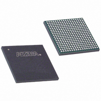
EP20K100EFC324-2 Altera, EP20K100EFC324-2 Datasheet - Page 45

EP20K100EFC324-2
Manufacturer Part Number
EP20K100EFC324-2
Description
IC APEX 20KE FPGA 100K 324-FBGA
Manufacturer
Altera
Series
APEX-20K®r
Datasheet
1.EP20K30ETC144-3.pdf
(117 pages)
Specifications of EP20K100EFC324-2
Number Of Logic Elements/cells
4160
Number Of Labs/clbs
416
Total Ram Bits
53248
Number Of I /o
246
Number Of Gates
263000
Voltage - Supply
1.71 V ~ 1.89 V
Mounting Type
Surface Mount
Operating Temperature
0°C ~ 85°C
Package / Case
324-FBGA
Family Name
APEX 20K
Number Of Usable Gates
100000
Number Of Logic Blocks/elements
4160
# Registers
26
# I/os (max)
246
Frequency (max)
250MHz
Process Technology
SRAM
Operating Supply Voltage (typ)
1.8V
Logic Cells
4160
Ram Bits
53248
Device System Gates
263000
Operating Supply Voltage (min)
1.71V
Operating Supply Voltage (max)
1.89V
Operating Temp Range
0C to 85C
Operating Temperature Classification
Commercial
Mounting
Surface Mount
Pin Count
324
Package Type
FBGA
Lead Free Status / RoHS Status
Contains lead / RoHS non-compliant
Available stocks
Company
Part Number
Manufacturer
Quantity
Price
Company:
Part Number:
EP20K100EFC324-2
Manufacturer:
ALTERA
Quantity:
18
Company:
Part Number:
EP20K100EFC324-2
Manufacturer:
PANASONIC
Quantity:
86
Company:
Part Number:
EP20K100EFC324-2
Manufacturer:
ALTERA
Quantity:
25
Company:
Part Number:
EP20K100EFC324-2-3
Manufacturer:
VISHAY
Quantity:
15 000
Company:
Part Number:
EP20K100EFC324-2X
Manufacturer:
ALTERA
Quantity:
15
Altera Corporation
f
Figure 29. APEX 20KE I/O Banks
Notes to
(1)
(2)
Power Sequencing & Hot Socketing
Because APEX 20K and APEX 20KE devices can be used in a mixed-
voltage environment, they have been designed specifically to tolerate any
possible power-up sequence. Therefore, the V
supplies may be powered in any order.
For more information, please refer to the “Power Sequencing
Considerations” section in the Configuring APEX 20KE & APEX 20KC
Devices chapter of the Configuration Devices Handbook.
Signals can be driven into APEX 20K devices before and during power-up
without damaging the device. In addition, APEX 20K devices do not drive
out during power-up. Once operating conditions are reached and the
device is configured, APEX 20K and APEX 20KE devices operate as
specified by the user.
LVDS/LVPECL
Block (2)
Output
I/O Bank 8
I/O Bank 7
For more information on placing I/O pins in LVDS blocks, refer to the Guidelines for
Using LVDS Blocks section in Application Note 120 (Using LVDS in APEX 20KE
Devices).
If the LVDS input and output blocks are not used for LVDS, they can support all of
the I/O standards and can be used as input, output, or bidirectional pins with
V
CCIO
(1)
Figure
set to 3.3 V, 2.5 V, or 1.8 V.
29:
APEX 20K Programmable Logic Device Family Data Sheet
I/O Bank 6
I/O Bank 1
Regular I/O Blocks Support
■
■
■
■
■
■
■
■
■
■
■
■
LVTTL
LVCMOS
2.5 V
1.8 V
3.3 V PCI
LVPECL
HSTL Class I
GTL+
SSTL-2 Class I and II
SSTL-3 Class I and II
CTT
AGP
I/O Bank 2
I/O Bank 5
Individual
Power Bus
CCIO
and V
CCINT
I/O Bank 3
I/O Bank 4
(1)
LVDS/LVPECL
Block (2)
power
Input
45


