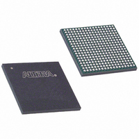
EP20K100EFC324-2 Altera, EP20K100EFC324-2 Datasheet - Page 50

EP20K100EFC324-2
Manufacturer Part Number
EP20K100EFC324-2
Description
IC APEX 20KE FPGA 100K 324-FBGA
Manufacturer
Altera
Series
APEX-20K®r
Datasheet
1.EP20K30ETC144-3.pdf
(117 pages)
Specifications of EP20K100EFC324-2
Number Of Logic Elements/cells
4160
Number Of Labs/clbs
416
Total Ram Bits
53248
Number Of I /o
246
Number Of Gates
263000
Voltage - Supply
1.71 V ~ 1.89 V
Mounting Type
Surface Mount
Operating Temperature
0°C ~ 85°C
Package / Case
324-FBGA
Family Name
APEX 20K
Number Of Usable Gates
100000
Number Of Logic Blocks/elements
4160
# Registers
26
# I/os (max)
246
Frequency (max)
250MHz
Process Technology
SRAM
Operating Supply Voltage (typ)
1.8V
Logic Cells
4160
Ram Bits
53248
Device System Gates
263000
Operating Supply Voltage (min)
1.71V
Operating Supply Voltage (max)
1.89V
Operating Temp Range
0C to 85C
Operating Temperature Classification
Commercial
Mounting
Surface Mount
Pin Count
324
Package Type
FBGA
Lead Free Status / RoHS Status
Contains lead / RoHS non-compliant
Available stocks
Company
Part Number
Manufacturer
Quantity
Price
Company:
Part Number:
EP20K100EFC324-2
Manufacturer:
ALTERA
Quantity:
18
Company:
Part Number:
EP20K100EFC324-2
Manufacturer:
PANASONIC
Quantity:
86
Company:
Part Number:
EP20K100EFC324-2
Manufacturer:
ALTERA
Quantity:
25
Company:
Part Number:
EP20K100EFC324-2-3
Manufacturer:
VISHAY
Quantity:
15 000
Company:
Part Number:
EP20K100EFC324-2X
Manufacturer:
ALTERA
Quantity:
15
APEX 20K Programmable Logic Device Family Data Sheet
50
f
f
f
f
t
f
t
t
t
OUT
CLK1
CLK2
CLK4
OUTDUTY
CLKDEV
R
F
LOCK
Table 15. APEX 20K ClockLock & ClockBoost Parameters for -1 Speed-Grade Devices (Part 1 of 2)
Symbol
(1)
Output frequency
Input clock frequency (ClockBoost clock
multiplication factor equals 1)
Input clock frequency (ClockBoost clock
multiplication factor equals 2)
Input clock frequency (ClockBoost clock
multiplication factor equals 4)
Duty cycle for ClockLock/ClockBoost-generated
clock
Input deviation from user specification in the
Quartus II software (ClockBoost clock
multiplication factor equals 1)
Input rise time
Input fall time
Time required for ClockLock/ClockBoost to
acquire lock
(4)
Figure 30. Specifications for the Incoming & Generated Clocks
Note to
(1)
Table 15
parameters for -1 speed-grade devices.
ClockLock
Generated
Clock
The tI parameter refers to the nominal input clock period; the tO parameter refers
to the nominal output clock period.
Parameter
Input
Clock
Figure
summarizes the APEX 20K ClockLock and ClockBoost
t
30:
R
(2)
f
CLK1
t
OUTDUTY
f
CLK4
,
t
f
F
CLK2
,
t
INDUTY
t
t
O
O
t
t
I +
O +
Min
t
25
25
16
10
40
t
INCLKSTB
JITTER
t
O
t
JITTER
25,000
180
Max
180
90
48
60
10
5
5
t
(1)
I +
Altera Corporation
(3)
t
CLKDEV
Note (1)
PPM
MHz
MHz
MHz
MHz
Unit
ns
ns
µs
%


