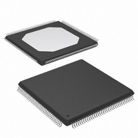
XC3S100E-4TQG144I Xilinx Inc, XC3S100E-4TQG144I Datasheet - Page 80

XC3S100E-4TQG144I
Manufacturer Part Number
XC3S100E-4TQG144I
Description
IC FPGA SPARTAN-3E 100K 144-TQFP
Manufacturer
Xilinx Inc
Series
Spartan™-3Er
Datasheet
1.XC3S100E-4TQG144I.pdf
(193 pages)
Specifications of XC3S100E-4TQG144I
Package / Case
144-TQFP, 144-VQFP
Mounting Type
Surface Mount
Voltage - Supply
1.1 V ~ 3.465 V
Operating Temperature
-40°C ~ 100°C
Number Of I /o
108
Number Of Logic Elements/cells
*
Number Of Gates
*
Lead Free Status / RoHS Status
Lead free / RoHS Compliant
Available stocks
Company
Part Number
Manufacturer
Quantity
Price
Company:
Part Number:
XC3S100E-4TQG144I
Manufacturer:
XILINX/21
Quantity:
163
Company:
Part Number:
XC3S100E-4TQG144I
Manufacturer:
Xilinx Inc
Quantity:
10 000
Part Number:
XC3S100E-4TQG144I
Manufacturer:
XILINX/赛灵思
Quantity:
20 000
High, the HSWAP pin is available as full-featured user-I/O
pin and is powered by the VCCO_0 supply.
The RDWR_B and CSI_B must be Low throughout the con-
figuration process. After configuration, these pins also
become user I/O.
In a single-FPGA application, the FPGA’s CSO_B and
CCLK pins are not used but are actively driving during the
configuration process. The BUSY pin is not used but also
Table 51: Byte-Wide Peripheral Interface (BPI) Connections
DS312-2 (v1.1) March 21, 2005
Advance Product Specification
HSWAP
M[2:0]
CSI_B
RDWR_B
LDC0
LDC1
HDC
LDC2
Pin Name
P
A
D
R
FPGA Direction
Output
Output
Output
Output
Input
Input
Input
Input
User I/O Pull-Up Control. When
Low during configuration, enables
pull-up resistors in all I/O pins to
respective I/O bank V
0: Pull-ups during configuration
1: No pull-ups
Mode Select. Selects the FPGA
configuration mode.
Chip Select Input. Active Low.
Read/Write Control. Active Low
write enable. Read functionality
typically only used after
configuration, if bitstream option
Persist=Yes .
PROM Chip Enable
PROM Output Enable
PROM Write Enable
PROM Byte Mode
Description
CCO
www.xilinx.com
input.
actively drives during configuration and is available as a
user I/O after configuration.
After configuration, all of the interface pins except DONE
and PROG_B are available as user I/Os. Furthermore, the
bidirectional SelectMAP configuration peripheral interface
(see
To continue using SelectMAP mode, set the Persist bit-
stream generator option to Yes . An external host can then
read and verify configuration data.
Drive at valid logic level
throughout configuration.
M2 = 0, M1 = 1. Set M0 = 0 to
start at address 0, increment
addresses. Set M0 = 1 to start at
address 0xFFFFFF and
decrement addresses. Sampled
when INIT_B goes High.
Must be Low throughout
configuration.
Must be Low throughout
configuration.
Connect to PROM chip-select
input (CE#). FPGA drives this
signal Low throughout
configuration.
Connect to PROM output-enable
input (OE#). FPGA drives this
signal Low throughout
configuration.
Connect to PROM write-enable
input (WE#). FPGA drives this
signal High throughout
configuration.
This signal is not used for x8
PROMs. For PROMs with a
x8/x16 data width control,
connect to PROM byte-mode
input (BYTE#). See
Using x8/x16 Flash
FPGA drives this signal Low
throughout configuration.
Slave Parallel
During Configuration
Precautions
Mode) is available after configuration.
PROMs.
Functional Description
User I/O
User I/O
User I/O. If bitstream
option Persist=Yes ,
becomes part of
SelectMap parallel
peripheral interface.
User I/O. If bitstream
option Persist=Yes ,
becomes part of
SelectMap parallel
peripheral interface.
User I/O
User I/O
User I/O
User I/O. Drive this pin
High after configuration to
use a x8/x16 PROM in
x16 mode.
After Configuration
73


