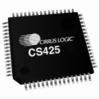
CS42528-DQZ Cirrus Logic Inc, CS42528-DQZ Datasheet - Page 65

CS42528-DQZ
Manufacturer Part Number
CS42528-DQZ
Description
IC CODEC S/PDIF RCVR 64-LQFP
Manufacturer
Cirrus Logic Inc
Type
Audio Codecr
Datasheet
1.CS42528-CQZ.pdf
(91 pages)
Specifications of CS42528-DQZ
Data Interface
Serial
Resolution (bits)
24 b
Number Of Adcs / Dacs
2 / 8
Sigma Delta
Yes
Dynamic Range, Adcs / Dacs (db) Typ
114 / 114
Voltage - Supply, Analog
4.75 V ~ 5.25 V
Voltage - Supply, Digital
3.13 V ~ 5.25 V
Operating Temperature
-40°C ~ 85°C
Mounting Type
Surface Mount
Package / Case
64-LQFP
Audio Codec Type
Stereo
No. Of Adcs
2
No. Of Dacs
8
No. Of Input Channels
2
No. Of Output Channels
8
Adc / Dac Resolution
24bit
Adcs / Dacs Signal To Noise Ratio
114dB
Lead Free Status / RoHS Status
Lead free / RoHS Compliant
For Use With
598-1503 - BOARD EVAL FOR CS42528/CS49300
Lead Free Status / RoHS Status
Lead free / RoHS Compliant, Lead free / RoHS Compliant
Available stocks
Company
Part Number
Manufacturer
Quantity
Price
Company:
Part Number:
CS42528-DQZ
Manufacturer:
Cirrus Logic Inc
Quantity:
10 000
Company:
Part Number:
CS42528-DQZR
Manufacturer:
Cirrus Logic Inc
Quantity:
10 000
DS586F1
6.22
6.23
6.23.1 S/PDIF RECEIVER LOCKING MODE (LOCKMX)
6.23.2 DATA BUFFER SELECT (BSEL)
UNLOCK1
UNLOCK0
LOCKM1
7
7
Interrupt Mode MSB (address 22h)
Interrupt Mode LSB (address 23h)
Channel Status Data Buffer Control (address 24h)
Default = 00000000
Function:
The two Interrupt Mode registers form a 2-bit code for each Interrupt Status register function. There
are three ways to set the INT pin active in accordance with the interrupt condition. In the Rising edge
active mode, the INT pin becomes active on the arrival of the interrupt condition. In the Falling edge
active mode, the INT pin becomes active on the removal of the interrupt condition. In Level active
mode, the INT interrupt pin becomes active during the interrupt condition. Be aware that the active
level (Active High or Low) only depends on the INT(1:0) bits located in the register
Control (address 1Eh)” on page
00 - Rising edge active
01 - Falling edge active
10 - Level active
11 - Reserved
Default = 01
00 - Revision C compatibility mode.
01 - Revision D default mode. Provides improved wideband jitter rejection in Double- and Quad-
10 - High update rate phase detector mode. Provides improved in-band jitter, but increased wideband
11 - Reserved.
Function:
Selects the mode used by the S/PDIF receiver to lock to the active RXP[7:0] input. Revision C com-
patibility mode is included for backward compatibility with Revision C.
Default = 0
0 - Data buffer address space contains Channel Status data
1 - Data buffer address space contains User data
Function:
Selects the data buffer register addresses to contain either User data or Channel Status data.
Reserved
Reserved
LOCKM0
Speed modes.
jitter. Use this setting for best ADC and DAC performance with clocked from the PLL recovered
clock.
6
6
Reserved
QCH1
QCH0
5
5
Reserved
DETC1
DETC0
61.
4
4
Reserved
DETU1
DETU0
3
3
Reserved
Reserved
BSEL
2
2
CAM
OF1
OF0
1
1
“Receiver Mode
CS42528
RERR1
RERR0
CHS
0
0
65


