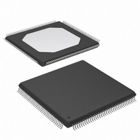
XCCACE-TQG144I Xilinx Inc, XCCACE-TQG144I Datasheet - Page 12

XCCACE-TQG144I
Manufacturer Part Number
XCCACE-TQG144I
Description
IC ACE CONTROLLER CHIP TQ144
Manufacturer
Xilinx Inc
Datasheet
1.XCCACE-TQG144I.pdf
(69 pages)
Specifications of XCCACE-TQG144I
Controller Type
ACE Controller
Voltage - Supply
3 V ~ 3.6 V
Current - Supply
30mA
Operating Temperature
-40°C ~ 85°C
Mounting Type
Surface Mount
Package / Case
144-TQFP, 144-VQFP
Lead Free Status / RoHS Status
Lead free / RoHS Compliant
Interface
-
Other names
122-1511-5
Available stocks
Company
Part Number
Manufacturer
Quantity
Price
Company:
Part Number:
XCCACE-TQG144I
Manufacturer:
XILINX
Quantity:
100
Part Number:
XCCACE-TQG144I
Manufacturer:
XILINX/赛灵思
Quantity:
20 000
Part Number:
XCCACE-TQG144ILEADFREE
Manufacturer:
XILINX/赛灵思
Quantity:
20 000
System ACE CompactFlash Solution
Table 6: MPU Interface Port Signal Description (Continued)
MPU Timing Description
This section contains timing diagrams for the MPU interface. Parameters used in the timing diagrams are described in
Table
Table 7: MPU Interface Timing Parameters
Single Register Read Cycle
The single register read cycle is shown in
page
ing a valid address (MPA), asserting the chip enable (MPCE
= LOW) and de-asserting the write enable (MPWE = HIGH)
during the first clock cycle (Cycle 0). These signals should
hold these values at least until the rising edge of the fourth
clock cycle (Cycle 3).
12
tSA
tSCE
tSWE
tSOE
tSD
tDD
tDOE
tDBRDY
tH
MPBRDY
MPIRQ
MPWE
MPOE
Name
Symbol
13. A single register read is accomplished by assert-
7.
Width
1
1
1
1
Address setup time
Chip enable setup time
Write enable setup time
Output enable setup time
Data setup time
Clock HIGH to valid data
Chip/Output enable LOW to valid data
Clock HIGH to buffer ready valid
Hold time
Direction
Out
Out
In
In
Active
HIGH
HIGH
LOW
LOW
Synchronous active LOW write enable. A high-to-low-to-high transition must
occur on MPWE in three consecutive clock cycles in order for the write to take
place.During a valid write cycle, MPCE must be LOW and MPD must be valid
during the clock cycle that MPWE.
Asynchronous active LOW output enable. Both MPOE and MPCE must be
LOW to read from the MPU interface. When either MPOE or MPCE is HIGH,
the MPD pins of the System ACE CF controller are in a high-impedance state.
Synchronous active HIGH buffer ready output. During data buffer read mode
MPBRDY is HIGH when the data in the DATABUF buffer is valid. During data
buffer write mode MPBRDY is HIGH when data can be written to the
DATABUF buffer.
Synchronous active HIGH interrupt request output. MPIRQ HIGH indicates
that an interrupt condition has occurred in the MPU interface. All interrupt
conditions must be manually cleared before MPIRQ will go LOW. MPIRQ is
always LOW when interrupts are disabled.
Parameter
Figure 9,
www.xilinx.com
The output enable signal should be asserted (MPOE =
LOW) during the third clock cycle (Cycle 2). Register data
associated with the specified address appears on the MPD
bus two clock cycles after the falling edge of MPCE during
the assertion of MPCE. The register read cycle is then com-
pleted by de-asserting the output enable during the fourth
clock cycle (Cycle 3).
Description
Min
12
12
--
--
--
4
4
4
4
DS080 (v2.0) October 1, 2008
Product Specification
Max
22
13
22
--
--
--
--
--
--
Units
ns
ns
ns
ns
ns
ns
ns
ns
ns
R


