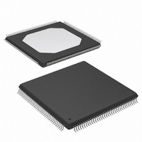
XCCACE-TQG144I Xilinx Inc, XCCACE-TQG144I Datasheet - Page 9

XCCACE-TQG144I
Manufacturer Part Number
XCCACE-TQG144I
Description
IC ACE CONTROLLER CHIP TQ144
Manufacturer
Xilinx Inc
Datasheet
1.XCCACE-TQG144I.pdf
(69 pages)
Specifications of XCCACE-TQG144I
Controller Type
ACE Controller
Voltage - Supply
3 V ~ 3.6 V
Current - Supply
30mA
Operating Temperature
-40°C ~ 85°C
Mounting Type
Surface Mount
Package / Case
144-TQFP, 144-VQFP
Lead Free Status / RoHS Status
Lead free / RoHS Compliant
Interface
-
Other names
122-1511-5
Available stocks
Company
Part Number
Manufacturer
Quantity
Price
Company:
Part Number:
XCCACE-TQG144I
Manufacturer:
XILINX
Quantity:
100
Part Number:
XCCACE-TQG144I
Manufacturer:
XILINX/赛灵思
Quantity:
20 000
Part Number:
XCCACE-TQG144ILEADFREE
Manufacturer:
XILINX/赛灵思
Quantity:
20 000
System ACE CF Directory Structure
A basic understanding of the typical System ACE CF file
and directory structure (shown in
programming an FPGA target system with a CompactFlash
device in the System ACE solution.
The ACE file is at the lowest level of the directory structure.
The Xilinx iMPACT software converts a revision of a design
(bitstream) into an ACE file. An ACE file represents a single
set of bitstreams for a particular chain of devices.
The next level up in the file structure is a collection. The col-
lection consists of eight ACE files grouped together. All of
the ACE files in a collection (directory) can be addressed
when in the System ACE CF environment. There can be
several collections stored on a CompactFlash device, but
only one collection can be active at any given time.
The
which designs can be read.
The hierarchical design of the System ACE CF directory
structure provides the ability to maintain multiple revisions
or collections of different designs in a single CompactFlash
DS080 (v2.0) October 1, 2008
Product Specification
xilinx.sys
CompactFlash
Project Name - (root dir) "/"
Containing Active Collection
R
dir = Rev_3;
cfgaddr0 = asia;
cfgaddr1 = europe;
cfgaddr3 = samerica;
cfgaddr4 = diag_1;
cfgaddr5 = diag_1;
cfgaddr6 = diag_2;
cfgaddr7 = diag_2;
(Up to 8 Designs)
ACE System File
xilinx.sys
file determines the collection from
Figure
Figure 8: System ACE Directory Structure
Rev_1 (sub-dir)
Rev_2 (sub-dir)
Rev_3 (sub-dir)
8) is useful when
(sub-dir)
*.ace
asia
www.xilinx.com
Available Collections
Collection Rev_3 Available Designs
for Target FPGA Chain
device. Each collection directory can contain one or more
designs that reside in different subdirectories. Each design
subdirectory should contain a single ACE file that repre-
sents a single set of bitstreams for a particular chain of
devices. In addition to FPGA configuration information, the
collection and design subdirectories can contain other infor-
mation pertaining to the system design such as system soft-
ware, documentation, etc.
The xilinx.sys file in the root directory of the Compact-
Flash device is used to control which of the designs within
the active collection is to be used to configure the chain of
target devices. Only one collection, containing up to eight
designs, can be active at one time.
The System ACE CF controller parses the xilinx.sys
file to determine the active collection designs and uses the
three configuration address pins or MPU register bits
(CFGADDR)
xilinx.sys file exists in the root directory of the Com-
pactFlash device, a single ACE file in the root directory is
used by System ACE as the active design.
(sub-dir)
europe
*.ace
to
select
System ACE CompactFlash Solution
the
(sub-dir)
diag_2
desired
*.ace
design.
DS080_11_032101
If
no
9


