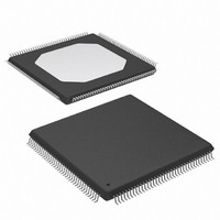
XCCACE-TQG144I Xilinx Inc, XCCACE-TQG144I Datasheet - Page 3

XCCACE-TQG144I
Manufacturer Part Number
XCCACE-TQG144I
Description
IC ACE CONTROLLER CHIP TQ144
Manufacturer
Xilinx Inc
Datasheet
1.XCCACE-TQG144I.pdf
(69 pages)
Specifications of XCCACE-TQG144I
Controller Type
ACE Controller
Voltage - Supply
3 V ~ 3.6 V
Current - Supply
30mA
Operating Temperature
-40°C ~ 85°C
Mounting Type
Surface Mount
Package / Case
144-TQFP, 144-VQFP
Lead Free Status / RoHS Status
Lead free / RoHS Compliant
Interface
-
Other names
122-1511-5
Available stocks
Company
Part Number
Manufacturer
Quantity
Price
Company:
Part Number:
XCCACE-TQG144I
Manufacturer:
XILINX
Quantity:
100
Part Number:
XCCACE-TQG144I
Manufacturer:
XILINX/赛灵思
Quantity:
20 000
Part Number:
XCCACE-TQG144ILEADFREE
Manufacturer:
XILINX/赛灵思
Quantity:
20 000
System ACE CF Controller
The System ACE CF controller manages FPGA configura-
tion data. The controller provides an intelligent interface
between an FPGA target chain and various supported con-
figuration sources; it can target multiple FPGA devices
using JTAG at a selectable throughput of up to 16.7
The directory structure used by the System ACE CF con-
troller enables it to support both CompactFlash and Hitachi
Microdrive devices through the CompactFlash port.
The MPU interface has access to the CompactFlash port,
the Configuration JTAG port, and local control/status fea-
tures. The Test JTAG port is used when doing Bound-
ary-Scan testing of the target FPGA chain or the System
ACE CF controller. Details about each interface are dis-
cussed below.
DS080 (v2.0) October 1, 2008
Product Specification
R
Control
Status
MPU
and
Figure 3: System ACE CF Controller Block Diagram
CompactFlash Port
Configuration JTAG (CFGJTAG) Port
(Target FPGA Chain)
www.xilinx.com
JTAG Controller
CompactFlash
CompactFlash
Configuration
Controller
Arbiter
Mbits/sec. As shown in
able for configuring a target FPGA chain through the Con-
figuration JTAG Port. These interfaces are: CompactFlash,
Microprocessor (MPU), and Test JTAG.
The System ACE CF controller has two main power sup-
plies: the core power supply (V
Flash/Test JTAG interface power supply (V
power source supplies the Test JTAG and CompactFlash
port levels. These two interfaces must be powered at 3.3V.
The V
uration JTAG ports, which can be run at 3.3V or 2.5V. It is
important to note that the MPU and Configuration JTAG
interfaces are always powered at the same voltage. Consid-
erations for the interface voltage are discussed in
Configuration Modes, page
CCL
core power source supplies the MPU and Config-
System ACE CompactFlash Solution
Figure
Test Scan
Interface
(LEDs,
37. See
Misc.
JTAG
etc.)
3, three interfaces are avail-
CCL
Figure 4, page
) and a Compact-
DS080_04_030801
CCH
). The V
Typical
4.
CCH
3


