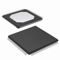
XCCACE-TQG144I Xilinx Inc, XCCACE-TQG144I Datasheet - Page 48

XCCACE-TQG144I
Manufacturer Part Number
XCCACE-TQG144I
Description
IC ACE CONTROLLER CHIP TQ144
Manufacturer
Xilinx Inc
Datasheet
1.XCCACE-TQG144I.pdf
(69 pages)
Specifications of XCCACE-TQG144I
Controller Type
ACE Controller
Voltage - Supply
3 V ~ 3.6 V
Current - Supply
30mA
Operating Temperature
-40°C ~ 85°C
Mounting Type
Surface Mount
Package / Case
144-TQFP, 144-VQFP
Lead Free Status / RoHS Status
Lead free / RoHS Compliant
Interface
-
Other names
122-1511-5
Available stocks
Company
Part Number
Manufacturer
Quantity
Price
Company:
Part Number:
XCCACE-TQG144I
Manufacturer:
XILINX
Quantity:
100
Part Number:
XCCACE-TQG144I
Manufacturer:
XILINX/赛灵思
Quantity:
20 000
Part Number:
XCCACE-TQG144ILEADFREE
Manufacturer:
XILINX/赛灵思
Quantity:
20 000
System ACE CompactFlash Solution
Writing Sector Data to CompactFlash Control
Flow Process
Sector data can be written to the CompactFlash device via
the MPU interface of the System ACE CF controller by fol-
lowing the control flow sequence shown in
first step in the sequence of accessing the CompactFlash
interface is to arbitrate for a lock. The control flow process
48
Set WriteMemCardData
Figure 28: Write Data to CompactFlash Control Flow Process
Reset configuration
Command Control
Write Data Buffer
Decrement Buffer
Write Data to CF
Return success.
Check If Ready
Count variable*
Initialize Buffer
Data is written.
Count variable
For Command
Set MPU LBA
Count Control
Get CF Lock
Set Sector
controller
Figure
28. The
*Set Buffer Count variable equal to
the number of buffers in a sector transfer
= ((Sector Count)*(512 Bytes per sector))/
= (Sector Count) * (16 buffers per sector)
www.xilinx.com
(32 bytes per buffer)
Write LBA bits 7:0 to byte address 10h
Write LBA bits 15:8 to byte address 11h
Write LBA bits 23:16 to byte address 12h
Write LBA bits 27:24 to byte address 13h
Write SECCNT bits 7:0 to byte address 14h
Write CFGRESET bit = 1 to byte address 18h
Clear configuration
Write CMD bits to byte address 15h
Release CF Lock
controller reset
Buffer Count
equal to 0?
for obtaining a CompactFlash resource lock is shown in
Figure 23, page
granted a CompactFlash lock, the MPU interface needs to
make sure that the CompactFlash device is ready to receive
a command. The process for polling the command readi-
ness indicator is shown in
No
Yes
43. Once the MPU interface has been
bit = 0 to byte
address 18h
Write LOCKREQ
Write CFGRESET
bit = 0 to byte
address 18h
DS080_053_051701
Figure 24, page
DS080 (v2.0) October 1, 2008
Product Specification
44.
R


