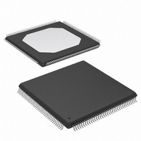
XCCACE-TQG144I Xilinx Inc, XCCACE-TQG144I Datasheet - Page 41

XCCACE-TQG144I
Manufacturer Part Number
XCCACE-TQG144I
Description
IC ACE CONTROLLER CHIP TQ144
Manufacturer
Xilinx Inc
Datasheet
1.XCCACE-TQG144I.pdf
(69 pages)
Specifications of XCCACE-TQG144I
Controller Type
ACE Controller
Voltage - Supply
3 V ~ 3.6 V
Current - Supply
30mA
Operating Temperature
-40°C ~ 85°C
Mounting Type
Surface Mount
Package / Case
144-TQFP, 144-VQFP
Lead Free Status / RoHS Status
Lead free / RoHS Compliant
Interface
-
Other names
122-1511-5
Available stocks
Company
Part Number
Manufacturer
Quantity
Price
Company:
Part Number:
XCCACE-TQG144I
Manufacturer:
XILINX
Quantity:
100
Part Number:
XCCACE-TQG144I
Manufacturer:
XILINX/赛灵思
Quantity:
20 000
Part Number:
XCCACE-TQG144ILEADFREE
Manufacturer:
XILINX/赛灵思
Quantity:
20 000
Reading Sector Data from CompactFlash Control
Flow Process
Sector data can be read from the CompactFlash device via
the MPU interface of the System ACE CF controller by fol-
lowing the control flow sequence shown in
first step in the sequence of accessing the CompactFlash
interface is to arbitrate for a lock. The control flow process
DS080 (v2.0) October 1, 2008
Product Specification
R
Figure 22: Reading Sector Data from CompactFlash Control Flow Process
Set ReadMemCardData
Read Data from CF
Reset configuration
Command Control
Read Data Buffer
Decrement Buffer
Return success.
Check If Ready
Count variable*
Initialize Buffer
Count variable
For Command
Set MPU LBA
Count Control
Get CF Lock
Data is read.
Set Sector
controller
Figure
22. The
*Set Buffer Count variable equal to
the number of buffers in a sector transfer
= ((Sector Count)*(512 Bytes per sector))/
= (Sector Count) * (16 buffers per sector)
www.xilinx.com
(32 bytes per buffer)
• Write LBA bits 7:0 to byte address 10h
Write LBA bits 15:8 to byte address 11h
Write LBA bits 23:16 to byte address 12h
Write LBA bits 27:24 to byte address 13h
Write SECCNT bits 7:0 to byte address 14h
W rite CFGRESET bit = 1 to byte address 18h
Write CMD bits to byte address 15h
Clear configuration
Release CF Lock
controller reset
Buffer Count
equal to 0?
for obtaining a CompactFlash resource lock is shown in
Figure 23, page
granted a CompactFlash lock, the MPU interface needs to
make sure that the CompactFlash device is ready to receive
a command. The process for polling the command readi-
ness indicator is shown in
No
Yes
43. Once the MPU interface has been
bit = 0 to byte
address 18h
W rite LOCKREQ
System ACE CompactFlash Solution
W rite CFGRESET
bit = 0 to byte
address 18h
DS080_48_051701
Figure 24, page
44.
41


