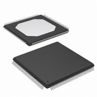
XCCACE-TQG144I Xilinx Inc, XCCACE-TQG144I Datasheet - Page 50

XCCACE-TQG144I
Manufacturer Part Number
XCCACE-TQG144I
Description
IC ACE CONTROLLER CHIP TQ144
Manufacturer
Xilinx Inc
Datasheet
1.XCCACE-TQG144I.pdf
(69 pages)
Specifications of XCCACE-TQG144I
Controller Type
ACE Controller
Voltage - Supply
3 V ~ 3.6 V
Current - Supply
30mA
Operating Temperature
-40°C ~ 85°C
Mounting Type
Surface Mount
Package / Case
144-TQFP, 144-VQFP
Lead Free Status / RoHS Status
Lead free / RoHS Compliant
Interface
-
Other names
122-1511-5
Available stocks
Company
Part Number
Manufacturer
Quantity
Price
Company:
Part Number:
XCCACE-TQG144I
Manufacturer:
XILINX
Quantity:
100
Part Number:
XCCACE-TQG144I
Manufacturer:
XILINX/赛灵思
Quantity:
20 000
Part Number:
XCCACE-TQG144ILEADFREE
Manufacturer:
XILINX/赛灵思
Quantity:
20 000
System ACE CompactFlash Solution
Write Data Buffer Control Flow Process
The control flow process for writing to the data buffer is
shown in
is implemented as a 32-byte (16-word) deep FIFO that is
aliased across a range of MPU byte addresses (40h
through 7Fh) in order to facilitate burst transfers across the
MPU interface. Sector data is written to the data buffer by
first waiting for the buffer to become ready (i.e., empty of
Microprocessor (MPU) to Configuration JTAG (CFGJTAG) Setup
This setup provides an MPU to CFGJTAG communication path. The data configures the FPGA system through JTAG via the
Configuration JTAG Port.
The System ACE CF controller handles all necessary steps to perform configuration using the MPU communication path to
the target system.
50
Figure 29, page
MPU
Figure 31, page 51
CFGTDO
49. The System ACE data buffer
Controller
ACE
Core
TDI
CompactFlash
Figure 30: Data Flow Diagram of MPU to CFGJTAG
shows the connections required for this setup.
CTRL.
TAP
B S
CFGTDI
TDO
C
(Configuration JTAG Port)
A
TDI
N
TSTTDI
TSTTDO
www.xilinx.com
*CFCGTCK and CFGTMS lines are driven
by ACE Controller Core Logic and are broadcast
to all target devices.
any sector data), as shown in
buffer is ready, then all 32 bytes can be written to the buffer
to alternating even and odd byte addresses. Writing to an
odd byte address while in BYTE mode causes the FIFO to
increment the data word to the next available word in the
FIFO. Writing to any data buffer address while in WORD
mode will cause the FIFO to increment.
TDO
TDO
TDI
TDI
TDO
Figure 26, page
DS080 (v2.0) October 1, 2008
(Test JTAG Port)
DS080_30_030801
Product Specification
46. Once the
R


