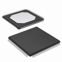
XCCACE-TQG144I Xilinx Inc, XCCACE-TQG144I Datasheet - Page 23

XCCACE-TQG144I
Manufacturer Part Number
XCCACE-TQG144I
Description
IC ACE CONTROLLER CHIP TQ144
Manufacturer
Xilinx Inc
Datasheet
1.XCCACE-TQG144I.pdf
(69 pages)
Specifications of XCCACE-TQG144I
Controller Type
ACE Controller
Voltage - Supply
3 V ~ 3.6 V
Current - Supply
30mA
Operating Temperature
-40°C ~ 85°C
Mounting Type
Surface Mount
Package / Case
144-TQFP, 144-VQFP
Lead Free Status / RoHS Status
Lead free / RoHS Compliant
Interface
-
Other names
122-1511-5
Available stocks
Company
Part Number
Manufacturer
Quantity
Price
Company:
Part Number:
XCCACE-TQG144I
Manufacturer:
XILINX
Quantity:
100
Part Number:
XCCACE-TQG144I
Manufacturer:
XILINX/赛灵思
Quantity:
20 000
Part Number:
XCCACE-TQG144ILEADFREE
Manufacturer:
XILINX/赛灵思
Quantity:
20 000
Table 11: STATUSREG Register Bit Descriptions (Continued)
DS080 (v2.0) October 1, 2008
Product Specification
Bit
10
11
12
13
14
15
16
17
18
19
8
9
4
5
6
7
CFDETECT
DATABUFRDY
DATABUFMODE
CFGDONE
RDYFORCFCMD
CFGMODEPIN
--
--
--
CFGADDRPIN0
CFGADDRPIN1
CFGADDRPIN2
--
CFBSY
CFRDY
CFDWF
R
Name
CompactFlash detect flag:
• 0 means that no CompactFlash device is connected to the System ACE CF controller
• 1 means that a CompactFlash is connected to the System ACE CF controller
Data buffer ready status:
• 0 means that the data buffer is not ready for data transfer
• 1 means that the data buffer is ready for data to be transferred out of the buffer when
Data buffer mode status:
• 0 means read-only mode
• 1 means write-only mode
Configuration DONE status:
• 0 means that the configuration process has not completed
• 1 means that the entire System ACE CF controller configuration file has been
Ready for CompactFlash controller command:
• 0 means not ready for command
• 1 means ready for command
Configuration mode pin (note that this can be overridden by the CFGMODE bit in the
CONTROLREG register):
• 1 means automatically start the configuration process immediately after System ACE
• 0 means wait for CFGSTART bit in CONTROLREG before starting the configuration
Reserved
Reserved
Reserved
Configuration address pins that are used as an offset into the system configuration file in
the CompactFlash device used to locate the System ACE CF controller configuration data
file (note that these pins can be overridden by the contents of the CFGADDRBIT[2:0] of
the CONTROLREG register)
Reserved
CompactFlash BUSY bit (reflects the state of the BSY bit in the status register of the
CompactFlash device):
• 0 means that the CompactFlash device is not busy
• 1 means that the CompactFlash command register and data buffer cannot be
CompactFlash ready for operation bit (reflects the state of the RDY bit in the status register
of the CompactFlash device):
• 0 means the CompactFlash device is NOT ready to accept commands
• 1 means CompactFlash device is ready to accept commands
CompactFlash data write fault bit (reflects the state of the DWF bit in the status register of
the CompactFlash device):
• 0 means that a write fault has NOT occurred
• 1 means that a write fault has occurred
reading from the CompactFlash controller or into the buffer when writing to the
CompactFlash or Configuration controller
executed and configuration of all devices in the target Boundary-Scan chain is
complete
CF controller Reset
process
accessed; Bits 18-23 of the STATUSREG register are not valid when this bit is set to 1
www.xilinx.com
Description
System ACE CompactFlash Solution
23


