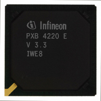
PXB4220E-V33 Infineon Technologies, PXB4220E-V33 Datasheet - Page 128

PXB4220E-V33
Manufacturer Part Number
PXB4220E-V33
Description
IC CHIPSET 8 E1/T1 LINE 256-BGA
Manufacturer
Infineon Technologies
Datasheet
1.PXB4220E-V33.pdf
(290 pages)
Specifications of PXB4220E-V33
Applications
*
Interface
*
Voltage - Supply
*
Package / Case
256-BGA
Mounting Type
Surface Mount
Lead Free Status / RoHS Status
Contains lead / RoHS non-compliant
Other names
PXB4220E-V33
PXB4220E-V33IN
PXB4220E-V33IN
Available stocks
Company
Part Number
Manufacturer
Quantity
Price
Company:
Part Number:
PXB4220E-V33
Manufacturer:
Intel
Quantity:
10
Company:
Part Number:
PXB4220E-V33
Manufacturer:
Infineon Technologies
Quantity:
10 000
- Current page: 128 of 290
- Download datasheet (4Mb)
x43_scram
bling
channel_
mode
ref_slot
Note: RAM slot 1 has always to be configured always as reference slot.
Note: To allow IWE8 internal initialization, all channels must remain in inactive mode for
6.1.2.2
Read/write Address 00400
Reset value: Not applicable. RAM must be reset and initialized via SW.
Data Sheet
31
23
15
7
at least 250 s after activation of the port (i.e. setting pcfN[p_tx_act] = 1). During
this time the device connected to the Framer Transmit Interface has to be in
normal operation.
RAM2: ATM Transmit Continuation Slot
ATM cell payload scrambling enable
0 =
1 =
Channel mode
00 =
01 =
10 =
11 =
Reference slot indicator
1 =
Not used
Disabled
Enabled
Inactive mode
Active mode (normal mode)
Standby mode
Active mode (normal mode)
This slot is a reference slot
H
to 005FF
Not used
Not used
Not used
H
128
scram-bli
PXB 4219E, PXB 4220E, PXB 4221E
x43_
ng
channel_mode[1:0]
Memory Structure
IWE8, V3.4
2003-01-20
ref_slot
= 1
24
16
8
0
Related parts for PXB4220E-V33
Image
Part Number
Description
Manufacturer
Datasheet
Request
R

Part Number:
Description:
IC CHIPSET 8 E1/T1 LINE 256-BGA
Manufacturer:
Infineon Technologies
Datasheet:

Part Number:
Description:
Interworking Element for 8 E1/T1 Lines
Manufacturer:
Infineon Technologies AG
Datasheet:

Part Number:
Description:
members of Infineon ATM Chipset
Manufacturer:
Infineon Technologies AG
Datasheet:

Part Number:
Description:
Manufacturer:
Infineon Technologies AG
Datasheet:

Part Number:
Description:
Manufacturer:
Infineon Technologies AG
Datasheet:

Part Number:
Description:
Manufacturer:
Infineon Technologies AG
Datasheet:

Part Number:
Description:
Manufacturer:
Infineon Technologies AG
Datasheet:

Part Number:
Description:
Manufacturer:
Infineon Technologies AG
Datasheet:

Part Number:
Description:
Manufacturer:
Infineon Technologies AG
Datasheet:

Part Number:
Description:
Manufacturer:
Infineon Technologies AG
Datasheet:

Part Number:
Description:
16-bit microcontroller with 2x2 KByte RAM
Manufacturer:
Infineon Technologies AG
Datasheet:

Part Number:
Description:
NPN silicon RF transistor
Manufacturer:
Infineon Technologies AG
Datasheet:

Part Number:
Description:
NPN silicon RF transistor
Manufacturer:
Infineon Technologies AG
Datasheet:

Part Number:
Description:
NPN silicon RF transistor
Manufacturer:
Infineon Technologies AG
Datasheet:

Part Number:
Description:
NPN silicon RF transistor
Manufacturer:
Infineon Technologies AG
Datasheet:


