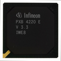
PXB4220E-V33 Infineon Technologies, PXB4220E-V33 Datasheet - Page 48

PXB4220E-V33
Manufacturer Part Number
PXB4220E-V33
Description
IC CHIPSET 8 E1/T1 LINE 256-BGA
Manufacturer
Infineon Technologies
Datasheet
1.PXB4220E-V33.pdf
(290 pages)
Specifications of PXB4220E-V33
Applications
*
Interface
*
Voltage - Supply
*
Package / Case
256-BGA
Mounting Type
Surface Mount
Lead Free Status / RoHS Status
Contains lead / RoHS non-compliant
Other names
PXB4220E-V33
PXB4220E-V33IN
PXB4220E-V33IN
Available stocks
Company
Part Number
Manufacturer
Quantity
Price
Company:
Part Number:
PXB4220E-V33
Manufacturer:
Intel
Quantity:
10
Company:
Part Number:
PXB4220E-V33
Manufacturer:
Infineon Technologies
Quantity:
10 000
- Current page: 48 of 290
- Download datasheet (4Mb)
The Loss of Cell Delineation (LCD) state is entered whenever the Out of Cell (OCD) state
is continuously active for more than an user defined period of time, ITU-T I.432.1
recommends a persistence time of 50ms.
For each port a separate timer is implemented. All timers can be enabled via the ´lcd_en´
bit in the LCD Timer Register (“lcdtimer”, see
defined by the “lcd_val” bits in lcdtimer. After expiration of each timer, an “lcd_start”
interrupt is generated, indicated in the Interrupt Status Register 1 (isr1, see
Chapter
If enabled, the timer is started at the transition from SYNC to OCD-state. After expiration
LCD state is entered. Whenever the SYNC state is entered before the timer expires, the
timer is reset.
The transition from LCD to Working state follows the same procedure. If after the LCD
state the SYNC state is entered again, the timer is started and after expiration the
maintenance state machine is in working state again. In parallel an “lcd_end” interrupt is
generated indicated in “isr1” and “eis0”. If synchronization is lost again during the timer
period, LCD state is reentered and the timer is reset.
To force resynchronization of the cell delineation process, the microprocessor can force
individual ports to enter the HUNT state, by setting the bit “go_hunt” in the corresponding
“ATM Receive Reference Slot” of RAM1
4.2.1.2
The Header Error Control (HEC) is implemented according to the ITU-T I.432.1 B-ISDN
user-network interface - Physical layer specification [33].
According to the HEC algorithm, cells are discarded when a multi-bit header error is
detected in the Correction mode or a header error is detected in the Detection mode.
According to the HEC algorithm, cells are corrected when a single-bit error is detected
in the Correction mode.
.
Figure 9
The pure HEC detection mode as recommended by the ATM Forum is selectable via bit
“a_hec_algor” in register acfg (see
Data Sheet
(No action)
detected
No error
7.18) and the Extended Interrupt Status Register 0 (eis0, see
HEC Check: Header Error Detection and Correction
HEC: Receiver mode of Operation (Figure 3/ITU I.432.1)
Corrrection
Mode
Single-bit error detected
Chapter
No error detected
(Cell discarded)
Multi-bit error
(Correction)
(No action)
detected
(Chapter
48
7.2)
PXB 4219E, PXB 4220E, PXB 4221E
Chapter
6.1.1.1).
7.43). The global preload value is
Detection
Mode
Operational Description
Chapter
(Cell discarded)
IWE8, V3.4
Error detected
2003-01-20
I432-1-Fig3
7.42).
Related parts for PXB4220E-V33
Image
Part Number
Description
Manufacturer
Datasheet
Request
R

Part Number:
Description:
IC CHIPSET 8 E1/T1 LINE 256-BGA
Manufacturer:
Infineon Technologies
Datasheet:

Part Number:
Description:
Interworking Element for 8 E1/T1 Lines
Manufacturer:
Infineon Technologies AG
Datasheet:

Part Number:
Description:
members of Infineon ATM Chipset
Manufacturer:
Infineon Technologies AG
Datasheet:

Part Number:
Description:
Manufacturer:
Infineon Technologies AG
Datasheet:

Part Number:
Description:
Manufacturer:
Infineon Technologies AG
Datasheet:

Part Number:
Description:
Manufacturer:
Infineon Technologies AG
Datasheet:

Part Number:
Description:
Manufacturer:
Infineon Technologies AG
Datasheet:

Part Number:
Description:
Manufacturer:
Infineon Technologies AG
Datasheet:

Part Number:
Description:
Manufacturer:
Infineon Technologies AG
Datasheet:

Part Number:
Description:
Manufacturer:
Infineon Technologies AG
Datasheet:

Part Number:
Description:
16-bit microcontroller with 2x2 KByte RAM
Manufacturer:
Infineon Technologies AG
Datasheet:

Part Number:
Description:
NPN silicon RF transistor
Manufacturer:
Infineon Technologies AG
Datasheet:

Part Number:
Description:
NPN silicon RF transistor
Manufacturer:
Infineon Technologies AG
Datasheet:

Part Number:
Description:
NPN silicon RF transistor
Manufacturer:
Infineon Technologies AG
Datasheet:

Part Number:
Description:
NPN silicon RF transistor
Manufacturer:
Infineon Technologies AG
Datasheet:


