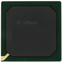
PEB20256E-V21 Infineon Technologies, PEB20256E-V21 Datasheet - Page 122

PEB20256E-V21
Manufacturer Part Number
PEB20256E-V21
Description
IC CONTROLLER INTERFACE 388-BGA
Manufacturer
Infineon Technologies
Datasheet
1.PEB20256E-V21.pdf
(232 pages)
Specifications of PEB20256E-V21
Function
Multichannel Network Interface Controller (MUNICH)
Interface
HDLC, PPP, Serial, TMA
Voltage - Supply
3 V ~ 3.6 V
Current - Supply
200mA
Power (watts)
3W
Operating Temperature
0°C ~ 70°C
Mounting Type
Surface Mount
Package / Case
388-BBGA
Lead Free Status / RoHS Status
Contains lead / RoHS non-compliant
Number Of Circuits
-
Other names
PEB20256E-V21
PEB20256E-V21IN
PEB20256E-V21IN
Available stocks
Company
Part Number
Manufacturer
Quantity
Price
Company:
Part Number:
PEB20256E-V21
Manufacturer:
MAX
Quantity:
63
Company:
Part Number:
PEB20256E-V21
Manufacturer:
Infineon Technologies
Quantity:
10 000
- Current page: 122 of 232
- Download datasheet (3Mb)
PEB 20256 E
PEF 20256 E
Reset and Initialization procedure
their initialization in progress signal. The register bit CONF1.IIP is the result of all signals.
As soon as all internal modules have finished their RAM initialization the register bit
CONF1.IIP is deasserted. Software must poll the register bit CONF1.IIP until this bit has
been deasserted. Read access to registers other than CONF1 is prohibited and may
result in unexpected behavior of the design. Write accesses are not allowed.
Chip initialization is finished when CONF1.IIP is ‘0’.
Software Reset
Alternately the MUNICH256 provides the capability to issue a software reset via register
bit CONF1.SRST. During software reset all interfaces except PCI interface are forced
into their idle state. After software reset is set the MUNICH256 starts its self initialization
and IIP will be asserted. Chip initialization is finished when CONF1.IIP is deasserted.
Afterwards the software reset bit must be set to ‘0’ to allow further operation.
7.2
Mode Initialization
After chip initialization is finished the system software has to setup the device for the
required function.
The system software has to poll bit CONF1.IIP (FCONF.IIP). As soon as CONF1.IIP is
deasserted, the system software has to clear bit CONF1.STOP and has to set the
general operating modes in register CONF1.
The port mode has to be programmed. It is assumed, that port clocks are active
according to the selected port mode. The ports shall be disabled, thus no incoming data
is forwarded to the time slot assigner and the outputs are still tri-state.
Transmit direction
The ports have to enabled via register TEN. The transmit port synchronizes to the
external synchronization pulse. After a port has been enabled payload data is provided
from the time slot assigner. Since the time slot assignment is in reset state, that is all time
slots are set to inhibit, data bits are tri-state.
Receive direction
The ports have to be enabled via register REN. The receiver synchronizes to the external
synchronization pulse. As soon as frame synchronization has been achieved, incoming
payload data is passed to the time slot assigner. Since the time slot assignment is in the
reset state, that is all time slots are set to inhibit, data bits are discarded.
Data Sheet
122
04.2001
Related parts for PEB20256E-V21
Image
Part Number
Description
Manufacturer
Datasheet
Request
R

Part Number:
Description:
Manufacturer:
Infineon Technologies AG
Datasheet:

Part Number:
Description:
Manufacturer:
Infineon Technologies AG
Datasheet:

Part Number:
Description:
Manufacturer:
Infineon Technologies AG
Datasheet:

Part Number:
Description:
Manufacturer:
Infineon Technologies AG
Datasheet:

Part Number:
Description:
Manufacturer:
Infineon Technologies AG
Datasheet:

Part Number:
Description:
Manufacturer:
Infineon Technologies AG
Datasheet:

Part Number:
Description:
Manufacturer:
Infineon Technologies AG
Datasheet:

Part Number:
Description:
16-bit microcontroller with 2x2 KByte RAM
Manufacturer:
Infineon Technologies AG
Datasheet:

Part Number:
Description:
NPN silicon RF transistor
Manufacturer:
Infineon Technologies AG
Datasheet:

Part Number:
Description:
NPN silicon RF transistor
Manufacturer:
Infineon Technologies AG
Datasheet:

Part Number:
Description:
NPN silicon RF transistor
Manufacturer:
Infineon Technologies AG
Datasheet:

Part Number:
Description:
NPN silicon RF transistor
Manufacturer:
Infineon Technologies AG
Datasheet:

Part Number:
Description:
Si-MMIC-amplifier in SIEGET 25-technologie
Manufacturer:
Infineon Technologies AG
Datasheet:

Part Number:
Description:
IGBT Power Module
Manufacturer:
Infineon Technologies AG
Datasheet:

Part Number:
Description:
IC for switching-mode power supplies
Manufacturer:
Infineon Technologies AG
Datasheet:


