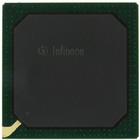
PEB20256E-V21 Infineon Technologies, PEB20256E-V21 Datasheet - Page 68

PEB20256E-V21
Manufacturer Part Number
PEB20256E-V21
Description
IC CONTROLLER INTERFACE 388-BGA
Manufacturer
Infineon Technologies
Datasheet
1.PEB20256E-V21.pdf
(232 pages)
Specifications of PEB20256E-V21
Function
Multichannel Network Interface Controller (MUNICH)
Interface
HDLC, PPP, Serial, TMA
Voltage - Supply
3 V ~ 3.6 V
Current - Supply
200mA
Power (watts)
3W
Operating Temperature
0°C ~ 70°C
Mounting Type
Surface Mount
Package / Case
388-BBGA
Lead Free Status / RoHS Status
Contains lead / RoHS non-compliant
Number Of Circuits
-
Other names
PEB20256E-V21
PEB20256E-V21IN
PEB20256E-V21IN
Available stocks
Company
Part Number
Manufacturer
Quantity
Price
Company:
Part Number:
PEB20256E-V21
Manufacturer:
MAX
Quantity:
63
Company:
Part Number:
PEB20256E-V21
Manufacturer:
Infineon Technologies
Quantity:
10 000
- Current page: 68 of 232
- Download datasheet (3Mb)
NO
THI
DescriptorID
NextTransmitDescriptorPointer
Data Sheet
Note: When repolling a descriptor the MUNICH256 checks the HOLD
Byte Number
The byte number defines the number of bytes stored in the data section
to be transmitted. Thus the maximum length of data buffer is 65535
bytes. In order to provide dummy transmit descriptors NO = 0 is allowed
in conjunction with the FE bit set. In this case (NO = 0) a ’Transmit Host
Initiated’ interrupt vector and/or the C-bit will be generated/set when the
data management unit recognizes this condition. It is an error to set
NO = 0 without FE bit set.
Transmit Host Initiated Interrupt
This bit indicates that the MUNICH256 shall generate a ’Transmit Host
Initiated’ interrupt vector after it has finished operating on the descriptor.
0
1
This bit field is read by the data management unit and written back in the
corresponding interrupt status of a channel interrupt vector which is
generated by data management unit. This value provides a link between
the descriptor and the corresponding interrupt vector.
This pointer contains the start address of the next transmit descriptor. It
has to be DWORD aligned. After sending the indicated number of data
bytes, the data management unit branches to the next transmit
descriptor. The transmit descriptor is read entirely at the beginning of
transmission and stored in on-chip memory. Therefore all informations in
the descriptor must be valid.
System CPU can force the MUNICH256 to branch to the beginning of a
new linked list via the command ’Transmit Abort/Branch’. In this case the
transmit descriptor address provided via register CSPEC_FTDA is used
as the next transmit descriptor pointer to be branched to.
the hold indication is still set, it stores further requests of the
receive buffer in its channel database. The channel can be
reactivated by issuing a ’Transmit Hold Reset’ command or by
providing a new linked list via the ’Transmit Abort/Branch’
command, in which case not served requests are processed.
bit and the bit field NextTransmitDescriptorPointer. All other
information are NOT updated in the internal channel database.
Data management unit does not generate an interrupt vector
after it has processed the transmit descriptor.
Data management unit generates an interrupt vector, as soon as
all data bytes are transferred to the internal transmit buffer and
the status information is updated.
68
Functional Description
PEB 20256 E
PEF 20256 E
04.2001
Related parts for PEB20256E-V21
Image
Part Number
Description
Manufacturer
Datasheet
Request
R

Part Number:
Description:
Manufacturer:
Infineon Technologies AG
Datasheet:

Part Number:
Description:
Manufacturer:
Infineon Technologies AG
Datasheet:

Part Number:
Description:
Manufacturer:
Infineon Technologies AG
Datasheet:

Part Number:
Description:
Manufacturer:
Infineon Technologies AG
Datasheet:

Part Number:
Description:
Manufacturer:
Infineon Technologies AG
Datasheet:

Part Number:
Description:
Manufacturer:
Infineon Technologies AG
Datasheet:

Part Number:
Description:
Manufacturer:
Infineon Technologies AG
Datasheet:

Part Number:
Description:
16-bit microcontroller with 2x2 KByte RAM
Manufacturer:
Infineon Technologies AG
Datasheet:

Part Number:
Description:
NPN silicon RF transistor
Manufacturer:
Infineon Technologies AG
Datasheet:

Part Number:
Description:
NPN silicon RF transistor
Manufacturer:
Infineon Technologies AG
Datasheet:

Part Number:
Description:
NPN silicon RF transistor
Manufacturer:
Infineon Technologies AG
Datasheet:

Part Number:
Description:
NPN silicon RF transistor
Manufacturer:
Infineon Technologies AG
Datasheet:

Part Number:
Description:
Si-MMIC-amplifier in SIEGET 25-technologie
Manufacturer:
Infineon Technologies AG
Datasheet:

Part Number:
Description:
IGBT Power Module
Manufacturer:
Infineon Technologies AG
Datasheet:

Part Number:
Description:
IC for switching-mode power supplies
Manufacturer:
Infineon Technologies AG
Datasheet:


