ATEVK1104 Atmel, ATEVK1104 Datasheet - Page 116
ATEVK1104
Manufacturer Part Number
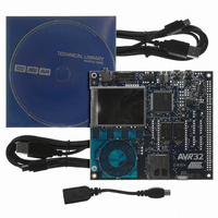
ATEVK1104
Description
KIT DEV/EVAL FOR AVR32 AT32UC3A
Manufacturer
Atmel
Series
AVR®32r
Type
MCUr
Datasheets
1.ATAVRONE-PROBECBL.pdf
(16 pages)
2.ATEVK1104.pdf
(826 pages)
3.ATEVK1104.pdf
(90 pages)
4.ATEVK1104.pdf
(6 pages)
5.ATEVK1104.pdf
(12 pages)
Specifications of ATEVK1104
Contents
Evaluation Board, Software and Documentation
Processor To Be Evaluated
AT32UC3A3
Data Bus Width
32 bit
Interface Type
USB, SPI, USART
Silicon Manufacturer
Atmel
Core Architecture
AVR
Core Sub-architecture
AVR UC3
Silicon Core Number
AT32UC3A3256
Silicon Family Name
AVR
Kit Contents
Board CD Docs
Rohs Compliant
Yes
For Use With/related Products
AT32UC3A3
Lead Free Status / RoHS Status
Lead free / RoHS Compliant
Available stocks
Company
Part Number
Manufacturer
Quantity
Price
Company:

Part Number:
ATEVK1104
Manufacturer:
Atmel
Quantity:
135


18.4
18.4.1
18.4.2
18.4.3
18.4.4
32058J–AVR32–04/11
Functional description
Bus interfaces
Memory organization
User page
Read operations
The FLASHC has two bus interfaces, one High-Speed Bus (HSB) interface for reads from the
flash array and writes to the page buffer, and one Peripheral Bus (PB) interface for writing
commands and control to and reading status from the controller.
To maximize performance for high clock-frequency systems, FLASHC interfaces to a flash
block with two read ports. The flash block has several parameters, given by the design of the
flash block. Refer to the “Memories” chapter for the device-specific values of the parameters.
The User page is an additional page, outside the regular flash array, that can be used to store
various data, like calibration data and serial numbers. This page is not erased by regular chip
erase. The User page can only be written and erased by proprietary commands. Read
accesses to the User page is performed just as any other read access to the flash. The
address map of the User page is given in
The FLASHC provides two different read modes:
Higher clock frequencies that would require more wait states are not supported by the flash
controller.
The programmer can select the wait states required by writing to the FWS field in the flash
control register (FCR). It is the responsibility of the programmer to select a number of wait
states compatible with the clock frequency and timing characteristics of the flash block.
In 0ws mode, only one of the two flash read ports is accessed. The other flash read port is idle.
In 1ws mode, both flash read ports are active. One read port reading the addressed word, and
the other reading the next sequential word.
If the clock frequency allows, the user should use 0ws mode, because this gives the lowest
power consumption for low-frequency systems as only one flash read port is read. Using 1ws
mode has a power/performance ratio approaching 0ws mode as the clock frequency
approaches twice the max frequency of 0ws mode. Using two flash read ports use twice the
power, but also give twice the performance.
• p pages (FLASH_P)
• w words in each page and in the page buffer (FLASH_W)
• pw words in total (FLASH_PW)
• f general-purpose fuse bits (FLASH_F)
• 1 security fuse bit
• 1 User Page
• 0 wait state (0ws) for clock frequencies < (access time of the flash plus the bus delay)
• 1 wait state (1ws) for clock frequencies < (access time of the flash plus the bus delay)/2
Figure
18-1.
AT32UC3A
116
Related parts for ATEVK1104
Image
Part Number
Description
Manufacturer
Datasheet
Request
R

Part Number:
Description:
DEV KIT FOR AVR/AVR32
Manufacturer:
Atmel
Datasheet:

Part Number:
Description:
INTERVAL AND WIPE/WASH WIPER CONTROL IC WITH DELAY
Manufacturer:
ATMEL Corporation
Datasheet:
Part Number:
Description:
Low-Voltage Voice-Switched IC for Hands-Free Operation
Manufacturer:
ATMEL Corporation
Datasheet:
Part Number:
Description:
MONOLITHIC INTEGRATED FEATUREPHONE CIRCUIT
Manufacturer:
ATMEL Corporation
Datasheet:
Part Number:
Description:
AM-FM Receiver IC U4255BM-M
Manufacturer:
ATMEL Corporation
Datasheet:
Part Number:
Description:
Monolithic Integrated Feature Phone Circuit
Manufacturer:
ATMEL Corporation
Datasheet:
Part Number:
Description:
Multistandard Video-IF and Quasi Parallel Sound Processing
Manufacturer:
ATMEL Corporation
Datasheet:
Part Number:
Description:
High-performance EE PLD
Manufacturer:
ATMEL Corporation
Datasheet:
Part Number:
Description:
8-bit Flash Microcontroller
Manufacturer:
ATMEL Corporation
Datasheet:
Part Number:
Description:
2-Wire Serial EEPROM
Manufacturer:
ATMEL Corporation
Datasheet: