ATEVK1104 Atmel, ATEVK1104 Datasheet - Page 522
ATEVK1104
Manufacturer Part Number
ATEVK1104
Description
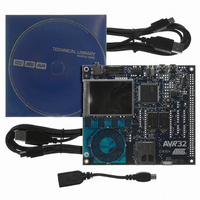
KIT DEV/EVAL FOR AVR32 AT32UC3A
Manufacturer
Atmel
Series
AVR®32r
Type
MCUr
Datasheets
1.ATAVRONE-PROBECBL.pdf
(16 pages)
2.ATEVK1104.pdf
(826 pages)
3.ATEVK1104.pdf
(90 pages)
4.ATEVK1104.pdf
(6 pages)
5.ATEVK1104.pdf
(12 pages)
Specifications of ATEVK1104
Contents
Evaluation Board, Software and Documentation
Processor To Be Evaluated
AT32UC3A3
Data Bus Width
32 bit
Interface Type
USB, SPI, USART
Silicon Manufacturer
Atmel
Core Architecture
AVR
Core Sub-architecture
AVR UC3
Silicon Core Number
AT32UC3A3256
Silicon Family Name
AVR
Kit Contents
Board CD Docs
Rohs Compliant
Yes
For Use With/related Products
AT32UC3A3
Lead Free Status / RoHS Status
Lead free / RoHS Compliant
Available stocks
Company
Part Number
Manufacturer
Quantity
Price
Company:

Part Number:
ATEVK1104
Manufacturer:
Atmel
Quantity:
135


30.7.3
30.7.3.1
Figure 30-22. USB Communication Flow
30.7.3.2
Figure 30-23. Host Mode States
32058J–AVR32–04/11
USB Host Operation
Description of Pipes
Power-On and Reset
For the USB controller in host mode, the term “pipe” is used instead of “endpoint” (used in
device mode). A host pipe corresponds to a device endpoint, as described by the
from the USB specification.
In host mode, the USB controller associates a pipe to a device endpoint, considering the device
configuration descriptors.
Figure 30-23
After a hardware reset, the USB controller host mode is in the Reset state.
When the USB macro is enabled (USBE = 1) in host mode (ID = 0), its host mode state goes to
the Idle state. In this state, the controller waits for device connection with minimal power con-
sumption. The USB pad should be in the Idle state. Once a device is connected, the macro
enters the Ready state, what does not require the USB clock to be activated.
describes the USB controller host mode main states.
Clock stopped
Ready
Device
Connection
Macro off
SOFE = 1
Device
Disconnection
SOFE = 0
Idle
Suspend
Device
Disconnection
state>
<any
other
AT32UC3A
Figure 30-22
522
Related parts for ATEVK1104
Image
Part Number
Description
Manufacturer
Datasheet
Request
R

Part Number:
Description:
DEV KIT FOR AVR/AVR32
Manufacturer:
Atmel
Datasheet:

Part Number:
Description:
INTERVAL AND WIPE/WASH WIPER CONTROL IC WITH DELAY
Manufacturer:
ATMEL Corporation
Datasheet:
Part Number:
Description:
Low-Voltage Voice-Switched IC for Hands-Free Operation
Manufacturer:
ATMEL Corporation
Datasheet:
Part Number:
Description:
MONOLITHIC INTEGRATED FEATUREPHONE CIRCUIT
Manufacturer:
ATMEL Corporation
Datasheet:
Part Number:
Description:
AM-FM Receiver IC U4255BM-M
Manufacturer:
ATMEL Corporation
Datasheet:
Part Number:
Description:
Monolithic Integrated Feature Phone Circuit
Manufacturer:
ATMEL Corporation
Datasheet:
Part Number:
Description:
Multistandard Video-IF and Quasi Parallel Sound Processing
Manufacturer:
ATMEL Corporation
Datasheet:
Part Number:
Description:
High-performance EE PLD
Manufacturer:
ATMEL Corporation
Datasheet:
Part Number:
Description:
8-bit Flash Microcontroller
Manufacturer:
ATMEL Corporation
Datasheet:
Part Number:
Description:
2-Wire Serial EEPROM
Manufacturer:
ATMEL Corporation
Datasheet: