ATEVK1104 Atmel, ATEVK1104 Datasheet - Page 56
ATEVK1104
Manufacturer Part Number
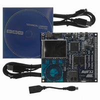
ATEVK1104
Description
KIT DEV/EVAL FOR AVR32 AT32UC3A
Manufacturer
Atmel
Series
AVR®32r
Type
MCUr
Datasheets
1.ATAVRONE-PROBECBL.pdf
(16 pages)
2.ATEVK1104.pdf
(826 pages)
3.ATEVK1104.pdf
(90 pages)
4.ATEVK1104.pdf
(6 pages)
5.ATEVK1104.pdf
(12 pages)
Specifications of ATEVK1104
Contents
Evaluation Board, Software and Documentation
Processor To Be Evaluated
AT32UC3A3
Data Bus Width
32 bit
Interface Type
USB, SPI, USART
Silicon Manufacturer
Atmel
Core Architecture
AVR
Core Sub-architecture
AVR UC3
Silicon Core Number
AT32UC3A3256
Silicon Family Name
AVR
Kit Contents
Board CD Docs
Rohs Compliant
Yes
For Use With/related Products
AT32UC3A3
Lead Free Status / RoHS Status
Lead free / RoHS Compliant
Available stocks
Company
Part Number
Manufacturer
Quantity
Price
Company:

Part Number:
ATEVK1104
Manufacturer:
Atmel
Quantity:
135


13.5.3
13.5.4
32058J–AVR32–04/11
32 KHz oscillator operation
PLL operation
The PM masks the oscillator outputs during the start-up time, to ensure that no unstable clocks
propagate to the digital logic. The OSCnRDY bits in POSCSR are automatically set and cleared
according to the status of the oscillators. A zero to one transition on these bits can also be con-
figured to generate an interrupt, as described in
page
Figure 13-2. Oscillator connections
The 32 KHz oscillator operates as described for Oscillator 0 and 1 above. The 32 KHz oscillator
is used as source clock for the Real-Time Counter.
The oscillator is disabled by default, but can be enabled by writing OSC32EN in OSCCTRL32.
The oscillator is an ultra-low power design and remains enabled in all sleep modes except Static
mode.
While the 32 KHz oscillator is disabled, the XIN32 and XOUT32 pins are available as general
purpose I/Os. When the oscillator is configured to work with an external clock (MODE field in
OSCCTRL32 register), the external clock must be connected to XIN32 while the XOUT32 pin
can be used as a general purpose I/O.
The startup time of the 32 KHz oscillator can be set in the OSCCTRL32, after which OSC32RDY
in POSCSR is set. An interrupt can be generated on a zero to one transition of OSC32RDY.
As a crystal oscillator usually requires a very long startup time (up to 1 second), the 32 KHz
oscillator will keep running across resets, except Power-On-Reset.
The device contains two PLLs, PLL0 and PLL1. These are disabled by default, but can be
enabled to provide high frequency source clocks for synchronous or generic clocks. The PLLs
can take either Oscillator 0 or 1 as reference clock. The PLL output is divided by a multiplication
factor, and the PLL compares the resulting clock to the reference clock. The PLL will adjust its
output frequency until the two compared clocks are equal, thus locking the output frequency to a
multiple of the reference clock frequency.
The Voltage Controlled Oscillator inside the PLL can generate frequencies from 80 to 240 MHz.
To make the PLL output frequencies under 80 MHz the OTP[1] bitfield could be set. This will
76.
XO U T
XIN
”Interrupt Enable/Disable/Mask/Status/Clear” on
C
C
2
1
AT32UC3A
56
Related parts for ATEVK1104
Image
Part Number
Description
Manufacturer
Datasheet
Request
R

Part Number:
Description:
DEV KIT FOR AVR/AVR32
Manufacturer:
Atmel
Datasheet:

Part Number:
Description:
INTERVAL AND WIPE/WASH WIPER CONTROL IC WITH DELAY
Manufacturer:
ATMEL Corporation
Datasheet:
Part Number:
Description:
Low-Voltage Voice-Switched IC for Hands-Free Operation
Manufacturer:
ATMEL Corporation
Datasheet:
Part Number:
Description:
MONOLITHIC INTEGRATED FEATUREPHONE CIRCUIT
Manufacturer:
ATMEL Corporation
Datasheet:
Part Number:
Description:
AM-FM Receiver IC U4255BM-M
Manufacturer:
ATMEL Corporation
Datasheet:
Part Number:
Description:
Monolithic Integrated Feature Phone Circuit
Manufacturer:
ATMEL Corporation
Datasheet:
Part Number:
Description:
Multistandard Video-IF and Quasi Parallel Sound Processing
Manufacturer:
ATMEL Corporation
Datasheet:
Part Number:
Description:
High-performance EE PLD
Manufacturer:
ATMEL Corporation
Datasheet:
Part Number:
Description:
8-bit Flash Microcontroller
Manufacturer:
ATMEL Corporation
Datasheet:
Part Number:
Description:
2-Wire Serial EEPROM
Manufacturer:
ATMEL Corporation
Datasheet: