XE8000EV108 Semtech, XE8000EV108 Datasheet - Page 126
XE8000EV108
Manufacturer Part Number
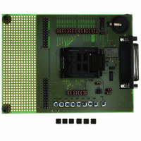
XE8000EV108
Description
EVAL BOARD FOR XE8806/XE8807
Manufacturer
Semtech
Type
MCUr
Specifications of XE8000EV108
Contents
Fully Assembled Evaluation Board
For Use With/related Products
XE88LC06AMI026
Lead Free Status / RoHS Status
Contains lead / RoHS non-compliant


17.6
Counters are enabled by CntAEnable, CntBEnable, CntCEnable, and CntDEnable in RegCntOn.
To stop the counter X, CntXEnable must be reset. To start the counter X, CntXEnable must be set. When
counters are cascaded, CntAEnable and CntCEnable also control respectively the counters B and D.
All counters have a corresponding 8-bit read/write register: RegCntA, RegCntB, RegCntC, and RegCntD. When
read, these registers contain the counter value (or the captured counter value). When written, they modify the
counter comparison values.
It is possible to read any counter at any time, even when the counter is running. The value is guaranteed to be
correct when the counter is running on an internal clock source. For a correct acquisition of the counter value when
running on an external clock source, use one of the three following methods:
When a value is written into the counter register while the counter is in counter mode, both the comparison value is
updated and the counter value is modified. In upcount mode, the register value is reset to zero. In downcount
mode, the comparison value is loaded into the counter. Due to the synchronization mechanism between the
processor clock domain and the external clock source domain, this modification of the counter value can be
postponed until the counter is enabled and that it receives it’s first valid clock edge.
In the PWM mode or in the capture mode, the counter value is not modified by the write operation in the counter
register. Changing to the counter mode, does not update the counter value (no reset in upcount, no load in
downcount mode).
17.7 Clock selection
The clock source for each counter can be individually selected by writing the appropriate value in the register
RegCntCtrlCk.
Table 17-11 gives the correspondence between the binary codes used for the configuration bits CntACkSel(1:0),
CntBCkSel(1:0), CntCCkSel(1:0) or CntDCkSel(1:0) and the clock source selected respectively for the counters
A, B, C or D.
The CkRcExt clock is the RC oscillator or external clock. The clocks below 32kHz can be derived from the RC
oscillator, the external clock source or the crystal oscillator (see the documentation of the clock block). A separate
external clock source can be delivered on PortA for each individula counter.
© Semtech 2006
1) For slow operating counters (typically at least 8 times slower than the CPU clock), oversample the counter
2) Stop the concerned counter, perform the read operation and restart the counter. While stopped, the
3) Use the capture mechanism.
General counter registers operation
content and perform a majority operation on the consecutive read results to select the correct actual
content of the counter.
counter content is frozen and the counter does not take into account the clock edges delivered on the
external pin.
CntXCkSel(1:0)
11
10
01
00
Table 17-11: Clock sources for counters A, B, C and D
CounterA
PA(0)
CkRcExt/4
CkRcExt
CounterB
17-5
PA(1)
Clock source for
Ck128
CounterC
PA(2)
Ck32k
Ck1k
XE8806A/XE8807A
CounterD
PA(3)
www.semtech.com
Related parts for XE8000EV108
Image
Part Number
Description
Manufacturer
Datasheet
Request
R

Part Number:
Description:
EVALUATION BOARD
Manufacturer:
Semtech
Datasheet:
Part Number:
Description:
EVALUATION BOARD
Manufacturer:
Semtech
Datasheet:
Part Number:
Description:
VOLTAGE SUPPRESSOR, TRANSIENT SEMTECH
Manufacturer:
Semtech
Datasheet:

Part Number:
Description:
HIGH VOLTAGE CAPACITORS MONOLITHIC CERAMIC TYPE
Manufacturer:
Semtech Corporation
Datasheet:
Part Number:
Description:
EZ1084CM5.0 AMP POSITIVE VOLTAGE REGULATOR
Manufacturer:
Semtech Corporation
Datasheet:
Part Number:
Description:
3.0 AMP LOW DROPOUT POSITIVE VOLTAGE REGULATORS
Manufacturer:
Semtech Corporation
Datasheet:
Part Number:
Description:
Manufacturer:
Semtech Corporation
Datasheet:
Part Number:
Description:
RailClamp Low Capacitance TVS Diode Array
Manufacturer:
Semtech Corporation
Datasheet:
Part Number:
Description:
Manufacturer:
Semtech Corporation
Datasheet:
Part Number:
Description:
Manufacturer:
Semtech Corporation
Datasheet:
Part Number:
Description:
Manufacturer:
Semtech Corporation
Datasheet:
Part Number:
Description:
Manufacturer:
Semtech Corporation
Datasheet: