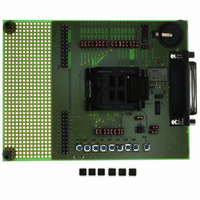
XE8000EV108 Semtech, XE8000EV108 Datasheet - Page 94

XE8000EV108
Manufacturer Part Number
XE8000EV108
Description
EVAL BOARD FOR XE8806/XE8807
Manufacturer
Semtech
Type
MCUr
Specifications of XE8000EV108
Contents
Fully Assembled Evaluation Board
For Use With/related Products
XE88LC06AMI026
Lead Free Status / RoHS Status
Contains lead / RoHS non-compliant
- Current page: 94 of 143
- Download datasheet (889Kb)
Even if the external bit synchronizer is used, the baud rate should be set correctly.
14.11 Specifications
If a frequency difference exists between the transmitter and the receiver, the receiver may be unable to decode the
received messages correctly. This is especially the case if no protocol or if the NRZ protocols are used without an
external bit synchronization clock since these signals do not contain clock information. Manchester and Miller
coding are more robust since the decoder can resynchronize on the code itself.
The estimated maximal tolerated frequency difference between the transmitter and the RF interface are the
following (theoretical values):
In NRZ without external bit synchronizer, it should be noted that the tolerated frequency deviation is larger if the
number of consecutive identical bits is lower than 10.
14.12 Application hints
Standard API functions to drive the XE1200 series are given in the TN8000.18. Using these API functions will allow
you to set-up a transmission between two systems very quickly.
Below, you will find some examples on how to set-up the RF circuits and the RF interface (BitJockey
14.12.1
This chapter gives some examples on how the RF interface can be used with the XE1201A circuit. It does not
describe all possibilities but selects some representative cases.
14.12.1.1 Microcontroller – transceiver connections
For the external components required to operate the XE1201A, please refer to the XE1201A datasheet.
The connections between the XE8000 microcontroller and the XE1201A are shown in Figure 14-8. The
transmission data pins are connected between the RF interface of the microcontroller and the transceiver. The
configuration lines of the XE1201A can be driven by pins of a parallel port. The 3-wire configuration data bus of the
XE1201A is used to set-up the circuit by writing in the registers A, B and C. The interface can be driven by a
hardware SPI or by a software SPI on a parallel port. Pins of the RF interface RFIF0 to RFIF3 that are not used
may remain floating.
© Semtech 2006
Using the RF interface with the XE1201A
NRZ, with external clock
NRZ, no external clock
Manchester
Mode
Miller
Table 14-19 : Frequency difference tolerance
RfifBRCoarse[1:0]
Table 14-18 : Effect of RfifBRCoarse[1:0]
00
01
10
11
14-14
Maximal tolerated ∆f=f
and consecutive bits: ±4%
to receive 10 identical
-50%/+100%
-17%/+11%
-9%/+8%
coarse
16
1
4
8
XE8806A/XE8807A
RX
-f
TX
TM
www.semtech.com
).
Related parts for XE8000EV108
Image
Part Number
Description
Manufacturer
Datasheet
Request
R

Part Number:
Description:
EVALUATION BOARD
Manufacturer:
Semtech
Datasheet:

Part Number:
Description:
EVALUATION BOARD
Manufacturer:
Semtech
Datasheet:

Part Number:
Description:
VOLTAGE SUPPRESSOR, TRANSIENT SEMTECH
Manufacturer:
Semtech
Datasheet:

Part Number:
Description:
HIGH VOLTAGE CAPACITORS MONOLITHIC CERAMIC TYPE
Manufacturer:
Semtech Corporation
Datasheet:

Part Number:
Description:
EZ1084CM5.0 AMP POSITIVE VOLTAGE REGULATOR
Manufacturer:
Semtech Corporation
Datasheet:

Part Number:
Description:
3.0 AMP LOW DROPOUT POSITIVE VOLTAGE REGULATORS
Manufacturer:
Semtech Corporation
Datasheet:

Part Number:
Description:
Manufacturer:
Semtech Corporation
Datasheet:

Part Number:
Description:
RailClamp Low Capacitance TVS Diode Array
Manufacturer:
Semtech Corporation
Datasheet:

Part Number:
Description:
Manufacturer:
Semtech Corporation
Datasheet:

Part Number:
Description:
Manufacturer:
Semtech Corporation
Datasheet:

Part Number:
Description:
Manufacturer:
Semtech Corporation
Datasheet:

Part Number:
Description:
Manufacturer:
Semtech Corporation
Datasheet:


