XE8000EV108 Semtech, XE8000EV108 Datasheet - Page 74
XE8000EV108
Manufacturer Part Number
XE8000EV108
Description
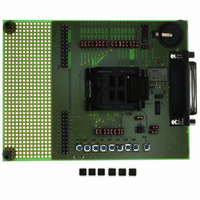
EVAL BOARD FOR XE8806/XE8807
Manufacturer
Semtech
Type
MCUr
Specifications of XE8000EV108
Contents
Fully Assembled Evaluation Board
For Use With/related Products
XE88LC06AMI026
Lead Free Status / RoHS Status
Contains lead / RoHS non-compliant


12.5.2
The table below defines the on-resistance of the switches between the pin and the analog bus for different
conditions. The series resistance between 2 pins of Port B connected to the same analog line is twice the
resistance given in the table.
Note 1: This is the series resistance between the pad and the analog line in 2 cases
Note 2: This is the series resistance in case VBAT ≥ 2.8V and the peripheral VMULT is not present on the circuit.
Note 3: This is the input capacitance seen on the pin when the pin is not connected to an analog line. This value is
indicative only since it is product and package dependent.
Note 4: This is the input capacitance seen on the pin when the pin is connected to an analog line and no other pin
is connected to the same analog line. This value is indicative only since it is product and package dependent.
12.6 Port B function capability
The Port B can be used for different functions implemented by other peripherals. The description below is
applicable only in so far the circuit contains these peripherals.
When the counters are used to implement a PWM function (see the documentation of the counters), the PB[0] and
PB[1] terminals are used as outputs (PB[0] is used if CntPWM0 in RegCntConfig1 is set to 1, PB[1] is used if
CntPWM1 in RegCntConfig1 is set to 1) and the PWM generated values override the values written in RegPBout.
However, PBDir(0) and PBDir(1) are not automatically overwritten and have to be set to 1.
If Output16k is set in RegSysMisc, the frequency is output on PB[3]. This overrides the value contained in
PBOut(3). However, PBDir(3) must be set to 1. The frequency and duty cycle of the clock signal are given in
Figure 12-1. f
Similarly, if OutputCkCpu is set in RegSysMisc, the CPU frequency is output on PB[2]. This overrides the value
contained in PBOut(2). However, PBDir(2) must be set to 1.
© Semtech 2006
sym
Ron
Ron
Cin
Cin
Table 12-10. Analog input specifications.
Port B analog function specification
description
switch resistance
switch resistance
input capacitance (off)
input capacitance (on)
max
1. VBAT ≥ 2.4V and the VMULT peripheral is present on the circuit and enabled.
2. VBAT ≥ 3.0V and the VMULT peripheral is not present on the circuit.
is the frequency of fastest clock present in the circuit.
Figure 12-1. 16 kHz output clock timing
1/fmax
1/f1
Figure 12-2. CPU output clock timing.
min
1/16k
1/f2
3.5
4.5
typ
12-5
max
15
11
unit
kΩ
kΩ
pF
pF
Comments
XE8806A/XE8807A
Note 1
Note 2
Note 3
Note 4
www.semtech.com
Related parts for XE8000EV108
Image
Part Number
Description
Manufacturer
Datasheet
Request
R

Part Number:
Description:
EVALUATION BOARD
Manufacturer:
Semtech
Datasheet:
Part Number:
Description:
EVALUATION BOARD
Manufacturer:
Semtech
Datasheet:
Part Number:
Description:
VOLTAGE SUPPRESSOR, TRANSIENT SEMTECH
Manufacturer:
Semtech
Datasheet:

Part Number:
Description:
HIGH VOLTAGE CAPACITORS MONOLITHIC CERAMIC TYPE
Manufacturer:
Semtech Corporation
Datasheet:
Part Number:
Description:
EZ1084CM5.0 AMP POSITIVE VOLTAGE REGULATOR
Manufacturer:
Semtech Corporation
Datasheet:
Part Number:
Description:
3.0 AMP LOW DROPOUT POSITIVE VOLTAGE REGULATORS
Manufacturer:
Semtech Corporation
Datasheet:
Part Number:
Description:
Manufacturer:
Semtech Corporation
Datasheet:
Part Number:
Description:
RailClamp Low Capacitance TVS Diode Array
Manufacturer:
Semtech Corporation
Datasheet:
Part Number:
Description:
Manufacturer:
Semtech Corporation
Datasheet:
Part Number:
Description:
Manufacturer:
Semtech Corporation
Datasheet:
Part Number:
Description:
Manufacturer:
Semtech Corporation
Datasheet:
Part Number:
Description:
Manufacturer:
Semtech Corporation
Datasheet: