XE8000EV108 Semtech, XE8000EV108 Datasheet - Page 68
XE8000EV108
Manufacturer Part Number
XE8000EV108
Description
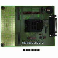
EVAL BOARD FOR XE8806/XE8807
Manufacturer
Semtech
Type
MCUr
Specifications of XE8000EV108
Contents
Fully Assembled Evaluation Board
For Use With/related Products
XE88LC06AMI026
Lead Free Status / RoHS Status
Contains lead / RoHS non-compliant


The snap-to-rail function connects a pullup or pulldown resistor to the input pin depending on the value forced on
the input pin. This function can be used for instance when the input port is connected to a tristate bus. When the
bus is floating, the pullup or pulldown maintains the bus in the last low impedance state before it became floating
until another low impedance output drives the bus. It also reduces the power consumption with respect to a classic
pullup since it selects the pullup or pulldown resistor so that it confirms the detected input state.
The state of input pin is summarized in the table below.
Port A starts up with the pullup resistor connected and the snap-to-rail function disabled.
Port A as an interrupt source:
Each Port A input is an interrupt request source and can be set on rising or falling edge with the corresponding bit
in RegPAEdge. After reset, the rising edge is selected for interrupt generation by default. The interrupt source can
be debounced by setting register RegPADebounce. The interrupt signals are sampled on the fastest clock in the
circuit. In order to guarantee that the circuit detects the interrupt, the minimal pulse length should be 1 cycle of this
clock.
Note: care must be taken when modifying RegPAEdge because this register performs an edge selection. The
change of this register may result in a transition, which may be interpreted as a valid interruption.
Port A as an event source:
The interrupt signals of the pins PA[0] and PA[1] are also available as events on the event controller.
Port A as a clock source (product dependent):
Images of the PA[0] to PA[3] input ports (debounced or not) are available as clock sources for the
counter/timer/PWM peripheral.
Port A as a reset source:
Port A can be used to generate a system reset by placing a predetermined word on Port A externally. The reset is
built using a logical and of the 8 PARes[x] signals:
PAReset[x] is itself a logical function of the corresponding pin PA[x]. One of four logical functions can be selected
for each pin by writing into two registers RegPARes0 and RegPARes1 as shown in Table 11-12.
A reset from Port A can be inhibited by placing a 0 on both PARes1[x] and PARes0[x] for at least 1 pin. Setting
both PARes1[x] and PARes0[x] to 1, makes the reset independent of the value on the corresponding pin. Setting
both registers to hFF, will reset the circuit independent from the Port A input value. This makes it possible to do a
reset by software.
© Semtech 2006
resetfromportA = PAReset[7] AND PAReset[6] AND PAReset[5] AND ... AND PAReset[0]
PAPullup[x]
0
1
1
1
PARes1[x]
0
0
1
1
Table 11-12: Selection bits for reset signal
PASnaptorail[x]
x
0
1
1
Table 11-11: Snap-to-rail
PARes0[x]
11-5
0
1
0
1
(last) externally
forced PA[x]
value
0
1
x
x
PAReset[x]
not(PA[x])
PA[x]
0
1
PA[x] pull
pulldown
XE8806A/XE8807A
floating
pullup
pullup
www.semtech.com
Related parts for XE8000EV108
Image
Part Number
Description
Manufacturer
Datasheet
Request
R

Part Number:
Description:
EVALUATION BOARD
Manufacturer:
Semtech
Datasheet:
Part Number:
Description:
EVALUATION BOARD
Manufacturer:
Semtech
Datasheet:
Part Number:
Description:
VOLTAGE SUPPRESSOR, TRANSIENT SEMTECH
Manufacturer:
Semtech
Datasheet:

Part Number:
Description:
HIGH VOLTAGE CAPACITORS MONOLITHIC CERAMIC TYPE
Manufacturer:
Semtech Corporation
Datasheet:
Part Number:
Description:
EZ1084CM5.0 AMP POSITIVE VOLTAGE REGULATOR
Manufacturer:
Semtech Corporation
Datasheet:
Part Number:
Description:
3.0 AMP LOW DROPOUT POSITIVE VOLTAGE REGULATORS
Manufacturer:
Semtech Corporation
Datasheet:
Part Number:
Description:
Manufacturer:
Semtech Corporation
Datasheet:
Part Number:
Description:
RailClamp Low Capacitance TVS Diode Array
Manufacturer:
Semtech Corporation
Datasheet:
Part Number:
Description:
Manufacturer:
Semtech Corporation
Datasheet:
Part Number:
Description:
Manufacturer:
Semtech Corporation
Datasheet:
Part Number:
Description:
Manufacturer:
Semtech Corporation
Datasheet:
Part Number:
Description:
Manufacturer:
Semtech Corporation
Datasheet: