XE8000EV108 Semtech, XE8000EV108 Datasheet - Page 87
XE8000EV108
Manufacturer Part Number
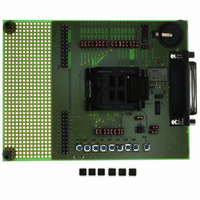
XE8000EV108
Description
EVAL BOARD FOR XE8806/XE8807
Manufacturer
Semtech
Type
MCUr
Specifications of XE8000EV108
Contents
Fully Assembled Evaluation Board
For Use With/related Products
XE88LC06AMI026
Lead Free Status / RoHS Status
Contains lead / RoHS non-compliant


14.8.1
14.8.1.1
When the NRZ codes are used, the bit synchronization clock should be extracted from the preamble since the
coding itself may not contain clock information. The input data filter has to be used (see description below in
section 14.8.1.2) to extract the bit synchronization clock. The bit RfifRxClock in register RegRfifCmd2 is to be
cleared to 0. If the input data stream contains long periods without transitions, the internally generated bit
synchronization clock could slip with respect to the bit rate resulting in transmission errors (see also specification in
chapter 14.11). Tests have shown a very robust behavior with the internal bit synchronizer though.
An external bit synchronization clock can be used. This clock has to be delivered on the pin RFIF1. The bit stream
on RFIF0 is then sampled on detection of the rising edge of the clock on the RFIF1 pin. This function has to be
enabled by setting bit RfifRxClock in register RegRfifCmd2 to 1. Selecting this function bypasses the input filter.
In practice, it was found that the synchronization was more reliable with the internal synchronization filter than with
the external bit clock.
14.8.1.2
The bi-phase and Miller code include clock information and no external bit synchronization clock is needed. The
input data filter is used to filter the noise on the input data. The filter samples the input data at 16 times the selected
baud rate and performs the following majority function on 8 successive samples:
if (number of ’1’ in the last 8 samples >= 6)
if (number of ‘1’ in the last 8 samples <= 2)
else data = former data
The filter has some hysteresis since the output does not change when the number of 1’s is between 2 and 6.
The input filter is always selected for the bi-phase and Miller coding independent from the value of the bit
RfifRxClock in register RegRfifCmd2.
14.8.2
A full message is mainly composed of three parts:
A start sequence is necessary to indicate the start of a new message.
The interface supports the detection of several types of start sequences. The user can chose between these start
sequence detection modes using the bits RfifEnStart[1:0] in RegRfifCmd2 as shown in Table 14-13. The actual
implementation of the detection mode differs depending on the selected PCM coding and is described below.
A start sequence detection will set the bit RfifRxStartDet in the register RegRfifRxSta and generate an interrupt
on the Irq_Rfif_Rx line. The contents of the reception FIFO is reset. The data of the preceding message that were
not yet read at the occurrence of a new start sequence are lost. The first bit in the FIFO is the first valid bit decoded
after the detected start sequence.
The bit RfifRxStartDet has to be cleared by software by writing a 1 to the bit.
© Semtech 2006
data = 1
data = 0
1) a preamble or start sequence
2) the data itself
3) an optional stop sequence.
Input data filter and bit synchronization
NRZ code
Bi-phase and Miller code
Start Sequence Detection or message synchronization
14-7
XE8806A/XE8807A
www.semtech.com
Related parts for XE8000EV108
Image
Part Number
Description
Manufacturer
Datasheet
Request
R

Part Number:
Description:
EVALUATION BOARD
Manufacturer:
Semtech
Datasheet:
Part Number:
Description:
EVALUATION BOARD
Manufacturer:
Semtech
Datasheet:
Part Number:
Description:
VOLTAGE SUPPRESSOR, TRANSIENT SEMTECH
Manufacturer:
Semtech
Datasheet:

Part Number:
Description:
HIGH VOLTAGE CAPACITORS MONOLITHIC CERAMIC TYPE
Manufacturer:
Semtech Corporation
Datasheet:
Part Number:
Description:
EZ1084CM5.0 AMP POSITIVE VOLTAGE REGULATOR
Manufacturer:
Semtech Corporation
Datasheet:
Part Number:
Description:
3.0 AMP LOW DROPOUT POSITIVE VOLTAGE REGULATORS
Manufacturer:
Semtech Corporation
Datasheet:
Part Number:
Description:
Manufacturer:
Semtech Corporation
Datasheet:
Part Number:
Description:
RailClamp Low Capacitance TVS Diode Array
Manufacturer:
Semtech Corporation
Datasheet:
Part Number:
Description:
Manufacturer:
Semtech Corporation
Datasheet:
Part Number:
Description:
Manufacturer:
Semtech Corporation
Datasheet:
Part Number:
Description:
Manufacturer:
Semtech Corporation
Datasheet:
Part Number:
Description:
Manufacturer:
Semtech Corporation
Datasheet: