XE8000EV108 Semtech, XE8000EV108 Datasheet - Page 85
XE8000EV108
Manufacturer Part Number
XE8000EV108
Description
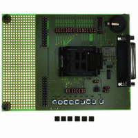
EVAL BOARD FOR XE8806/XE8807
Manufacturer
Semtech
Type
MCUr
Specifications of XE8000EV108
Contents
Fully Assembled Evaluation Board
For Use With/related Products
XE88LC06AMI026
Lead Free Status / RoHS Status
Contains lead / RoHS non-compliant


14.5 Interrupts
Two interrupt lines exist: one for the transmitter and one for the receiver.
14.6 External connections
The interface uses 4 I/O pins. The use of these pins depends on the set up of the interface. Table 14-11 shows the
possible use of these pins.
In receive mode, the pin RFIF0 is the receiver data stream input. If the external bit synchronization clock mode is
selected, the RFIF1 pin should be connected to the bit synchronizer clock of the receiver. If the receiver has a
message synchronization signal, it can be connected to RFIF2.
In transmitter mode, the transmitter data pin has to be connected to RFIF3. A bit synchronization clock can be
generated on RFIF2.
In case the RFIF pins are multiplexed on a parallel digital I/O port, the interface overwrites all four digital pins as
soon as the receive mode or transmitter mode of the interface are enabled (bit RfifEnRx or RfifEnTx in register
RegRfifCmd3 is set at 1).
Unused pins are configured as inputs with a weak pull-up or pull-down. These pins may remain floating or may be
driven externally. No external pull-ups or pull-downs are required.
14.7 Supported PCM codes
Seven different PCM codes are supported by the interface. They are illustrated in the figure below.
NRZ Code: in this format one message bit is represented by one chip (i.e. the distance between two dotted
lines in Figure 14-2). The coding does not include clock information. The bit sampling clock information has to be
extracted from the message preamble.
Bi-Phase Code or Manchester code: in this format one message bit is represented by two chips. This code
contains clock information.
Delay Modulation or Miller code: in this format one message bit is represented by two chips. This code
contains clock information.
The interface can receive and transmit coded or uncoded messages. The coding/decoding function is
enabled/disabled using the bit RfifEnCod (1 = enable) in the register RegRfifCmd2.
© Semtech 2006
Transmit mode
Receive mode
data in
RFIF0
-
Table 14-11 : PAD management
Table 14-10: Interrupts
interrupt source
Irq_Rfif_Rx
Irq_Rfif_Tx
RFIF1
clock
14-5
-
RFIF2
match
clock
XE8806A/XE8807A
data out
RFIF3
-
www.semtech.com
Related parts for XE8000EV108
Image
Part Number
Description
Manufacturer
Datasheet
Request
R

Part Number:
Description:
EVALUATION BOARD
Manufacturer:
Semtech
Datasheet:
Part Number:
Description:
EVALUATION BOARD
Manufacturer:
Semtech
Datasheet:
Part Number:
Description:
VOLTAGE SUPPRESSOR, TRANSIENT SEMTECH
Manufacturer:
Semtech
Datasheet:

Part Number:
Description:
HIGH VOLTAGE CAPACITORS MONOLITHIC CERAMIC TYPE
Manufacturer:
Semtech Corporation
Datasheet:
Part Number:
Description:
EZ1084CM5.0 AMP POSITIVE VOLTAGE REGULATOR
Manufacturer:
Semtech Corporation
Datasheet:
Part Number:
Description:
3.0 AMP LOW DROPOUT POSITIVE VOLTAGE REGULATORS
Manufacturer:
Semtech Corporation
Datasheet:
Part Number:
Description:
Manufacturer:
Semtech Corporation
Datasheet:
Part Number:
Description:
RailClamp Low Capacitance TVS Diode Array
Manufacturer:
Semtech Corporation
Datasheet:
Part Number:
Description:
Manufacturer:
Semtech Corporation
Datasheet:
Part Number:
Description:
Manufacturer:
Semtech Corporation
Datasheet:
Part Number:
Description:
Manufacturer:
Semtech Corporation
Datasheet:
Part Number:
Description:
Manufacturer:
Semtech Corporation
Datasheet: