XE8000EV108 Semtech, XE8000EV108 Datasheet - Page 98
XE8000EV108
Manufacturer Part Number
XE8000EV108
Description
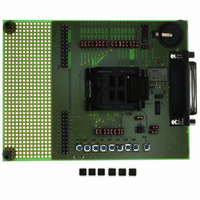
EVAL BOARD FOR XE8806/XE8807
Manufacturer
Semtech
Type
MCUr
Specifications of XE8000EV108
Contents
Fully Assembled Evaluation Board
For Use With/related Products
XE88LC06AMI026
Lead Free Status / RoHS Status
Contains lead / RoHS non-compliant


14.12.1.3.3
In order to handle the received data by interrupt, enable the RF interface reception interrupt in the interrupt handler
of the circuit.
Data received before the first start pattern detection after the enabling of the interface are not relevant since we are
not yet synchronized to the messages. Sine the start detection interrupt has been enabled, nothing has to be done
until the interrupt occurs.
When the first interrupt occurs, we are synchronized to the messages. In order to read data in an efficient way, the
interrupt source is modified and set to “Rx FIFO full” by writing 100 to RfifRxIrqEn. Once this is done, we can wait
for the next interrupt to download the received message.
At each new interrupt, we can now read 4 bytes of the received message by reading the register RegRfifRx 4
consecutive times. The interrupt should be served before the next byte is received since otherwise data may be
lost by lack of space in the FIFO (overrun error which sets the flag RfifRxFifoOverrun) or because the start
sequence of the next message is detected which resets the reception FIFO.
When the complete message is received, the start sequence detection interrupt may be enabled again
(RfifRxIrqEn = 001) and the sequence starts all over again.
14.12.1.4 Transmission mode using NRZ coding
The messages have to be sent encoded with NRZ Space. The start sequence of the message is 4 bytes of
“01010101”. The messages are sent at a data rate of 64 kbit/s and the modulator frequency deviation is 125kHz
and the output power is –5dbm.
The following paragraphs will show how to set-up the XE1201A, how to set-up the RF interface and how to handle
the transmission data.
14.12.1.4.1
To set the XE1201A in transmission mode, set the pin EN to 1 and the pin RXTX to 0. The modulator deviation
frequency is 125kHz by default and the output power is –5dbm by default, so there is no need to modify the
registers of the XE1201A.
14.12.1.4.2
Set-up the RF interface of the microcontroller circuit as a transmitter (RfifEnRx = 0 and RfifEnTx = 1).
Assume that the RC clock frequency used in the microcontroller is 1.0 MHz. To select the correct baud rate of 64
kbit/s according to the equation in chapter 14.10, fine*coarse=1.0e06/(16*64e3)=0.98. We can approximate this at
1, which is close enough (see specification in Table 14-19). This can be done by setting RfifBRCoarse = 00 and
RfifBRFine = 0000.
The external bit synchronization clock is switched off by clearing the bit RfifTxClock = 0.
The encoder is enabled and set to NRZ space encoding by setting RfifEnCod = 1 and RfifPCM = 010.
The set-up of the interface is summarized in the Table 14-24.
© Semtech 2006
Data reception
XE1201A set-up
RF interface set-up
RegRfifCmd1
RegRfifCmd2
RegRfifCmd3
Register
Table 14-24. RF interface set-up
14-18
00000000
00100010
00000001
contents
XE8806A/XE8807A
www.semtech.com
Related parts for XE8000EV108
Image
Part Number
Description
Manufacturer
Datasheet
Request
R

Part Number:
Description:
EVALUATION BOARD
Manufacturer:
Semtech
Datasheet:
Part Number:
Description:
EVALUATION BOARD
Manufacturer:
Semtech
Datasheet:
Part Number:
Description:
VOLTAGE SUPPRESSOR, TRANSIENT SEMTECH
Manufacturer:
Semtech
Datasheet:

Part Number:
Description:
HIGH VOLTAGE CAPACITORS MONOLITHIC CERAMIC TYPE
Manufacturer:
Semtech Corporation
Datasheet:
Part Number:
Description:
EZ1084CM5.0 AMP POSITIVE VOLTAGE REGULATOR
Manufacturer:
Semtech Corporation
Datasheet:
Part Number:
Description:
3.0 AMP LOW DROPOUT POSITIVE VOLTAGE REGULATORS
Manufacturer:
Semtech Corporation
Datasheet:
Part Number:
Description:
Manufacturer:
Semtech Corporation
Datasheet:
Part Number:
Description:
RailClamp Low Capacitance TVS Diode Array
Manufacturer:
Semtech Corporation
Datasheet:
Part Number:
Description:
Manufacturer:
Semtech Corporation
Datasheet:
Part Number:
Description:
Manufacturer:
Semtech Corporation
Datasheet:
Part Number:
Description:
Manufacturer:
Semtech Corporation
Datasheet:
Part Number:
Description:
Manufacturer:
Semtech Corporation
Datasheet: