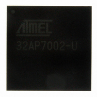
AT32AP7002-CTUT Atmel, AT32AP7002-CTUT Datasheet - Page 118

AT32AP7002-CTUT
Manufacturer Part Number
AT32AP7002-CTUT
Description
IC MCU 32BIT AVR32 196-CBGA
Manufacturer
Atmel
Series
AVR®32 AP7r
Specifications of AT32AP7002-CTUT
Core Processor
AVR
Core Size
32-Bit
Speed
150MHz
Connectivity
EBI/EMI, I²C, MMC, PS2, SPI, SSC, UART/USART, USB
Peripherals
AC'97, DMA, I²C, LCD, POR, PWM, WDT
Number Of I /o
85
Program Memory Type
ROMless
Ram Size
32K x 8
Voltage - Supply (vcc/vdd)
1.65 V ~ 1.95 V
Data Converters
D/A 2x16b
Oscillator Type
Internal
Operating Temperature
-40°C ~ 85°C
Package / Case
196-CBGA
Data Bus Width
32 bit
Data Ram Size
32 KB
Interface Type
I2C, JTAG, PS2, SPI, SSC, UART, USART, USB
Maximum Clock Frequency
150 MHz
Number Of Timers
3
Maximum Operating Temperature
+ 85 C
Mounting Style
SMD/SMT
Minimum Operating Temperature
- 40 C
On-chip Dac
16 bit, 2 Channel
Package
196CTBGA
Device Core
AVR32
Family Name
AT32
Maximum Speed
150 MHz
Operating Supply Voltage
1.8|3.3 V
For Use With
ATAVRONEKIT - KIT AVR/AVR32 DEBUGGER/PROGRMMRATNGW100 - KIT AVR32 NETWORK GATEWAYATSTK1000 - KIT STARTER FOR AVR32AP7000
Lead Free Status / RoHS Status
Lead free / RoHS Compliant
Eeprom Size
-
Program Memory Size
-
Lead Free Status / Rohs Status
Details
Available stocks
Company
Part Number
Manufacturer
Quantity
Price
- Current page: 118 of 896
- Download datasheet (13Mb)
11.4.2
11.4.3
11.4.4
11.5
11.5.1
11.5.1.1
11.5.1.2
11.5.1.3
32054F–AVR32–09/09
Functional Description
Power Management
Interrupt
Debug Operation
RTC operation
Source clock
Counter operation
RTC Interrupt
The RTC is continously clocked, and remains operating in all sleep modes except Static.
The RTC interrupt line is connected to one of the internal sources of the interrupt controller.
Using the RTC interrupt requires the interrupt controller to be programmed first.
The RTC prescaler and watchdog timer are frozen during debug operation, unless the OCD sys-
tem keeps peripherals running in debug operation.
The RTC is enabled by writing the EN bit in the CTRL register. This also enables the clock for
the prescaler. The PSEL bitfield in the same register selects the prescaler tapping, selecting the
source clock for the RTC:
Note that if the RTC is used in stop mode, PSEL must be 2 or higher to ensure no ticks are
missed when entering or leaving sleep mode.
The RTC count value can be read from or written to the register VAL. The prescaler cannot be
written directly, but can be reset by writing the strobe PCLR in CTRL.
When enabled, the RTC will then up-count until it reaches 0xFFFFFFFF, and then wrap to 0x0.
Writing CTRL:TOPEN to one causes the RTC to wrap at the value written to TOP. The status bit
TOPI in ISR is set when this occurs.
Writing the TOPI bit in IER enables the RTC interrupt, while writing the corresponding bit in IDR
disables the RTC interrupt. IMR can be read to see whether or not the interrupt is enabled. If
enabled, an interrupt will be generated if the TOPI flag in ISR is set. The flag can be cleared by
writing TOPI in ICR to one.
f
RTC
= 2
-(PSEL+1)
* 32KHz
AT32AP7002
118
Related parts for AT32AP7002-CTUT
Image
Part Number
Description
Manufacturer
Datasheet
Request
R

Part Number:
Description:
DEV KIT FOR AVR/AVR32
Manufacturer:
Atmel
Datasheet:

Part Number:
Description:
INTERVAL AND WIPE/WASH WIPER CONTROL IC WITH DELAY
Manufacturer:
ATMEL Corporation
Datasheet:

Part Number:
Description:
Low-Voltage Voice-Switched IC for Hands-Free Operation
Manufacturer:
ATMEL Corporation
Datasheet:

Part Number:
Description:
MONOLITHIC INTEGRATED FEATUREPHONE CIRCUIT
Manufacturer:
ATMEL Corporation
Datasheet:

Part Number:
Description:
AM-FM Receiver IC U4255BM-M
Manufacturer:
ATMEL Corporation
Datasheet:

Part Number:
Description:
Monolithic Integrated Feature Phone Circuit
Manufacturer:
ATMEL Corporation
Datasheet:

Part Number:
Description:
Multistandard Video-IF and Quasi Parallel Sound Processing
Manufacturer:
ATMEL Corporation
Datasheet:

Part Number:
Description:
High-performance EE PLD
Manufacturer:
ATMEL Corporation
Datasheet:

Part Number:
Description:
8-bit Flash Microcontroller
Manufacturer:
ATMEL Corporation
Datasheet:

Part Number:
Description:
2-Wire Serial EEPROM
Manufacturer:
ATMEL Corporation
Datasheet:


