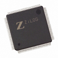
EZ80F92AZ020EG Zilog, EZ80F92AZ020EG Datasheet - Page 232

EZ80F92AZ020EG
Manufacturer Part Number
EZ80F92AZ020EG
Description
IC ACCLAIM MCU 128KB 100LQFP
Manufacturer
Zilog
Series
eZ80® Acclaim!®r
Specifications of EZ80F92AZ020EG
Core Processor
Z8
Core Size
8-Bit
Speed
20MHz
Connectivity
I²C, IrDA, SPI, UART/USART
Peripherals
Brown-out Detect/Reset, POR, WDT
Number Of I /o
24
Program Memory Size
128KB (128K x 8)
Program Memory Type
FLASH
Ram Size
8K x 8
Voltage - Supply (vcc/vdd)
3 V ~ 3.6 V
Oscillator Type
Internal
Operating Temperature
-40°C ~ 105°C
Package / Case
100-LQFP
Processor Series
EZ80F92x
Core
eZ80
Data Bus Width
8 bit
Data Ram Size
8 KB
Interface Type
I2C, IrDA, SPI, UART
Maximum Clock Frequency
20 MHz
Number Of Programmable I/os
24
Number Of Timers
6
Operating Supply Voltage
3 V to 3.6 V
Maximum Operating Temperature
+ 105 C
Mounting Style
SMD/SMT
Development Tools By Supplier
eZ80F920200ZCOG
Minimum Operating Temperature
- 40 C
Lead Free Status / RoHS Status
Lead free / RoHS Compliant
Eeprom Size
-
Data Converters
-
Lead Free Status / Rohs Status
Details
Other names
269-3871
EZ80F92AZ020EG
EZ80F92AZ020EG
Available stocks
Company
Part Number
Manufacturer
Quantity
Price
- Current page: 232 of 261
- Download datasheet (4Mb)
Table 145. DC Characteristics (Continued)
Table 146. POR and VBO Electrical Characteristics
PS015313-0508
Symbol
I
Notes
Symbol
V
V
V
T
T
V
RTC
ANA
VBO_MIN
VBO
POR
HYST
CC
1. This condition excludes all pins with on-chip pull-ups when driven Low.
2. RTC current increases when the eZ80F92 device is not in SLEEP mode as the RTC_VDD pin supplies power to
RAMP
system clock buffers within the Real-Time Clock circuit.
POR and VBO Electrical Characteristics
Typical Current Consumption Under Various Operating Conditions
Parameter
RTC Supply
Current
Parameter
VBO Voltage Threshold
POR Voltage Threshold
POR/VBO Hysteresis
POR/VBO analog RESET duration
VBO pulse reject period
V
guarantee proper RESET occurs
CC
Table 146
device.
In the following pages,
the eZ80F92 device versus the number of WAIT states while operating 25 ºC, 3.3 V, and
with either a 5 MHz, 10 MHz, 15 MHz, or 20 MHz system clock.
displays the typical current consumption of the eZ80F92 device versus the system clock
frequency while operating 25 ºC, 3.3 V, and using 0, 2, or 7 WAIT states.
page 227 displays the typical current consumption of the eZ80F92 device versus tempera-
ture while operating at 3.3 V, 7 WAIT states, and with either a 5 MHz, 10 MHz, 15 MHz
or 20 MHz system clock.
ramp rate requirements to
lists the Power-On Reset and Voltage Brownout characteristics of the eZ80F92
T
A
Min
2.5
= 0 ºC to 70 ºC
Figure 53
Figure 56
Typical
Max
10
on page 225 displays the typical current consumption of
on page 228 displays the typical current consumption
2.40
2.45
Min
0.1
T
50
40
A
T
= 0 ºC to +105 ºC
A
Min
2.5
= 0 ºC to 105 ºC
2.55
2.65
Typ
100
10
Typical
Max
10
Max
2.85
2.90
150
100
100
Units Conditions
V/ms
Unit Conditions
µA
mV
Product Specification
µs
µs
V
V
Figure 54
Electrical Characteristics
Supply current into
RTC_V
SLEEP mode
V
V
CC
CC
Figure 55
= V
= V
on page 226
DD
VBO
POR
;
2
on
.
224
Related parts for EZ80F92AZ020EG
Image
Part Number
Description
Manufacturer
Datasheet
Request
R

Part Number:
Description:
Communication Controllers, ZILOG INTELLIGENT PERIPHERAL CONTROLLER (ZIP)
Manufacturer:
Zilog, Inc.
Datasheet:

Part Number:
Description:
KIT DEV FOR Z8 ENCORE 16K TO 64K
Manufacturer:
Zilog
Datasheet:

Part Number:
Description:
KIT DEV Z8 ENCORE XP 28-PIN
Manufacturer:
Zilog
Datasheet:

Part Number:
Description:
DEV KIT FOR Z8 ENCORE 8K/4K
Manufacturer:
Zilog
Datasheet:

Part Number:
Description:
KIT DEV Z8 ENCORE XP 28-PIN
Manufacturer:
Zilog
Datasheet:

Part Number:
Description:
DEV KIT FOR Z8 ENCORE 4K TO 8K
Manufacturer:
Zilog
Datasheet:

Part Number:
Description:
CMOS Z8 microcontroller. ROM 16 Kbytes, RAM 256 bytes, speed 16 MHz, 32 lines I/O, 3.0V to 5.5V
Manufacturer:
Zilog, Inc.
Datasheet:

Part Number:
Description:
Low-cost microcontroller. 512 bytes ROM, 61 bytes RAM, 8 MHz
Manufacturer:
Zilog, Inc.
Datasheet:

Part Number:
Description:
Z8 4K OTP Microcontroller
Manufacturer:
Zilog, Inc.
Datasheet:

Part Number:
Description:
CMOS SUPER8 ROMLESS MCU
Manufacturer:
Zilog, Inc.
Datasheet:

Part Number:
Description:
SL1866 CMOSZ8 OTP Microcontroller
Manufacturer:
Zilog, Inc.
Datasheet:

Part Number:
Description:
SL1866 CMOSZ8 OTP Microcontroller
Manufacturer:
Zilog, Inc.
Datasheet:

Part Number:
Description:
OTP (KB) = 1, RAM = 125, Speed = 12, I/O = 14, 8-bit Timers = 2, Comm Interfaces Other Features = Por, LV Protect, Voltage = 4.5-5.5V
Manufacturer:
Zilog, Inc.
Datasheet:

Part Number:
Description:
Manufacturer:
Zilog, Inc.
Datasheet:


