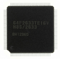
R5F61668RN50FPV Renesas Electronics America, R5F61668RN50FPV Datasheet - Page 1474

R5F61668RN50FPV
Manufacturer Part Number
R5F61668RN50FPV
Description
IC H8SX/1668 MCU FLASH 144LQFP
Manufacturer
Renesas Electronics America
Series
H8® H8SX/1600r
Datasheet
1.R5F61668RN50FPV.pdf
(1506 pages)
Specifications of R5F61668RN50FPV
Core Processor
H8SX
Core Size
16/32-Bit
Speed
50MHz
Connectivity
EBI/EMI, I²C, IrDA, SCI, SmartCard, USB
Peripherals
DMA, LVD, POR, PWM, WDT
Number Of I /o
92
Program Memory Size
1MB (1M x 8)
Program Memory Type
FLASH
Ram Size
56K x 8
Voltage - Supply (vcc/vdd)
3 V ~ 3.6 V
Data Converters
A/D 8x10b; D/A 2x8b
Oscillator Type
External
Operating Temperature
-20°C ~ 75°C
Package / Case
144-LQFP
For Use With
R0K561668S000BE - KIT STARTER FOR H8SX/1668R0K561664S001BE - KIT STARTER FOR H8SX/1651HS0005KCU11H - EMULATOR E10A-USB H8S(X),SH2(A)
Lead Free Status / RoHS Status
Lead free / RoHS Compliant
Eeprom Size
-
Available stocks
Company
Part Number
Manufacturer
Quantity
Price
Company:
Part Number:
R5F61668RN50FPV
Manufacturer:
Renesas Electronics America
Quantity:
10 000
- Current page: 1474 of 1506
- Download datasheet (9Mb)
Main Revisions and Additions in this Edition
Rev. 2.00 Sep. 24, 2008 Page 1440 of 1468
REJ09B0412-0200
Item
Section 18 Watchdog Timer
(WDT)
18.3.2 Timer Control/Status
Register
Section 19 Serial
Communication Interface
(SCI, IrDA, CRC)
19.3.12 IrDA Control Register
(IrCR)
Section 21 I
(IIC2)
21.1 Features
21.3.5 I
Register (ICSR)
21.7 Usage Notes
2
C Bus Status
2
C Bus Interface 2
1066
Page
858
911
1033
1047
1048
Revision (See Manual for Details)
Added
The description below for the bit 7 in the bit table is added:
(When the CPU is used to clear this flag while the
corresponding interrupt is enabled, be sure to read the flag
after writing 0 to it.)
Amended
The description below for the bit 7 in the bit table
1.TxD5/IrTxD and RxD5/IrRxD pins are operate as IrTxD
and IrRxD.
Added
Module stop function setting
Deleted
The description below for the bit 1 is deleted:
[Clearing condition]
When 0 is written to this bit after reading AAS = 1 (When
the CPU is used to clear this flag by writing 0 while the
corresponding interrupt is enabled, be sure to read the flag
after writing 0 to it.)
Deleted
The description below for the bit 0 is deleted:
[Clearing condition]
When 0 is written to this bit after reading ADZ = 1 (When
the CPU is used to clear this flag by writing 0 while the
corresponding interrupt is enabled, be sure to read the flag
after writing 0 to it.)
Added
6. Setting of the module stop function
Related parts for R5F61668RN50FPV
Image
Part Number
Description
Manufacturer
Datasheet
Request
R

Part Number:
Description:
KIT STARTER FOR M16C/29
Manufacturer:
Renesas Electronics America
Datasheet:

Part Number:
Description:
KIT STARTER FOR R8C/2D
Manufacturer:
Renesas Electronics America
Datasheet:

Part Number:
Description:
R0K33062P STARTER KIT
Manufacturer:
Renesas Electronics America
Datasheet:

Part Number:
Description:
KIT STARTER FOR R8C/23 E8A
Manufacturer:
Renesas Electronics America
Datasheet:

Part Number:
Description:
KIT STARTER FOR R8C/25
Manufacturer:
Renesas Electronics America
Datasheet:

Part Number:
Description:
KIT STARTER H8S2456 SHARPE DSPLY
Manufacturer:
Renesas Electronics America
Datasheet:

Part Number:
Description:
KIT STARTER FOR R8C38C
Manufacturer:
Renesas Electronics America
Datasheet:

Part Number:
Description:
KIT STARTER FOR R8C35C
Manufacturer:
Renesas Electronics America
Datasheet:

Part Number:
Description:
KIT STARTER FOR R8CL3AC+LCD APPS
Manufacturer:
Renesas Electronics America
Datasheet:

Part Number:
Description:
KIT STARTER FOR RX610
Manufacturer:
Renesas Electronics America
Datasheet:

Part Number:
Description:
KIT STARTER FOR R32C/118
Manufacturer:
Renesas Electronics America
Datasheet:

Part Number:
Description:
KIT DEV RSK-R8C/26-29
Manufacturer:
Renesas Electronics America
Datasheet:

Part Number:
Description:
KIT STARTER FOR SH7124
Manufacturer:
Renesas Electronics America
Datasheet:

Part Number:
Description:
KIT STARTER FOR H8SX/1622
Manufacturer:
Renesas Electronics America
Datasheet:

Part Number:
Description:
KIT DEV FOR SH7203
Manufacturer:
Renesas Electronics America
Datasheet:


