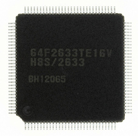
R5F61668RN50FPV Renesas Electronics America, R5F61668RN50FPV Datasheet - Page 30

R5F61668RN50FPV
Manufacturer Part Number
R5F61668RN50FPV
Description
IC H8SX/1668 MCU FLASH 144LQFP
Manufacturer
Renesas Electronics America
Series
H8® H8SX/1600r
Datasheet
1.R5F61668RN50FPV.pdf
(1506 pages)
Specifications of R5F61668RN50FPV
Core Processor
H8SX
Core Size
16/32-Bit
Speed
50MHz
Connectivity
EBI/EMI, I²C, IrDA, SCI, SmartCard, USB
Peripherals
DMA, LVD, POR, PWM, WDT
Number Of I /o
92
Program Memory Size
1MB (1M x 8)
Program Memory Type
FLASH
Ram Size
56K x 8
Voltage - Supply (vcc/vdd)
3 V ~ 3.6 V
Data Converters
A/D 8x10b; D/A 2x8b
Oscillator Type
External
Operating Temperature
-20°C ~ 75°C
Package / Case
144-LQFP
For Use With
R0K561668S000BE - KIT STARTER FOR H8SX/1668R0K561664S001BE - KIT STARTER FOR H8SX/1651HS0005KCU11H - EMULATOR E10A-USB H8S(X),SH2(A)
Lead Free Status / RoHS Status
Lead free / RoHS Compliant
Eeprom Size
-
Available stocks
Company
Part Number
Manufacturer
Quantity
Price
Company:
Part Number:
R5F61668RN50FPV
Manufacturer:
Renesas Electronics America
Quantity:
10 000
- Current page: 30 of 1506
- Download datasheet (9Mb)
Section 23 D/A Converter ............................................................................... 1097
23.1
23.2
23.3
23.4
23.5
Section 24 RAM .............................................................................................. 1103
Section 25 Flash Memory................................................................................ 1105
25.1
25.2
25.3
25.4
25.5
25.6
25.7
25.8
25.9
Rev. 2.00 Sep. 24, 2008 Page xxviii of xxxii
22.7.7
22.7.8
Features........................................................................................................................... 1097
Input/Output Pins............................................................................................................ 1098
Register Descriptions...................................................................................................... 1098
23.3.1
23.3.2
Operation ........................................................................................................................ 1101
Usage Notes .................................................................................................................... 1102
23.5.1
23.5.2
23.5.3
Features........................................................................................................................... 1105
Mode Transition Diagram............................................................................................... 1108
Memory MAT Configuration ......................................................................................... 1110
Block Structure ............................................................................................................... 1111
25.4.1
25.4.2
25.4.3
Programming/Erasing Interface ...................................................................................... 1114
Input/Output Pins............................................................................................................ 1116
Register Descriptions...................................................................................................... 1117
25.7.1
25.7.2
25.7.3
On-Board Programming Mode ....................................................................................... 1138
25.8.1
25.8.2
25.8.3
25.8.4
25.8.5
Protection........................................................................................................................ 1167
25.9.1
25.9.2
Notes on Board Design ................................................................................... 1095
Notes on Noise Countermeasures ................................................................... 1095
D/A Data Registers 0 and 1 (DADR0 and DADR1)....................................... 1098
D/A Control Register 01 (DACR01) .............................................................. 1099
Module Stop State Setting .............................................................................. 1102
D/A Output Hold Function in Software Standby Mode.................................. 1102
Notes on Deep Software Standby Mode ......................................................... 1102
Block Diagram of H8SX/1663........................................................................ 1111
Block Diagram of H8SX/1664........................................................................ 1112
Block Diagram of H8SX/1668........................................................................ 1113
Programming/Erasing Interface Registers ...................................................... 1118
Programming/Erasing Interface Parameters ................................................... 1125
RAM Emulation Register (RAMER).............................................................. 1137
Boot Mode ...................................................................................................... 1139
USB Boot Mode ............................................................................................. 1143
User Program Mode........................................................................................ 1147
User Boot Mode.............................................................................................. 1157
On-Chip Program and Storable Area for Program Data ................................. 1161
Hardware Protection ....................................................................................... 1167
Software Protection......................................................................................... 1168
Related parts for R5F61668RN50FPV
Image
Part Number
Description
Manufacturer
Datasheet
Request
R

Part Number:
Description:
KIT STARTER FOR M16C/29
Manufacturer:
Renesas Electronics America
Datasheet:

Part Number:
Description:
KIT STARTER FOR R8C/2D
Manufacturer:
Renesas Electronics America
Datasheet:

Part Number:
Description:
R0K33062P STARTER KIT
Manufacturer:
Renesas Electronics America
Datasheet:

Part Number:
Description:
KIT STARTER FOR R8C/23 E8A
Manufacturer:
Renesas Electronics America
Datasheet:

Part Number:
Description:
KIT STARTER FOR R8C/25
Manufacturer:
Renesas Electronics America
Datasheet:

Part Number:
Description:
KIT STARTER H8S2456 SHARPE DSPLY
Manufacturer:
Renesas Electronics America
Datasheet:

Part Number:
Description:
KIT STARTER FOR R8C38C
Manufacturer:
Renesas Electronics America
Datasheet:

Part Number:
Description:
KIT STARTER FOR R8C35C
Manufacturer:
Renesas Electronics America
Datasheet:

Part Number:
Description:
KIT STARTER FOR R8CL3AC+LCD APPS
Manufacturer:
Renesas Electronics America
Datasheet:

Part Number:
Description:
KIT STARTER FOR RX610
Manufacturer:
Renesas Electronics America
Datasheet:

Part Number:
Description:
KIT STARTER FOR R32C/118
Manufacturer:
Renesas Electronics America
Datasheet:

Part Number:
Description:
KIT DEV RSK-R8C/26-29
Manufacturer:
Renesas Electronics America
Datasheet:

Part Number:
Description:
KIT STARTER FOR SH7124
Manufacturer:
Renesas Electronics America
Datasheet:

Part Number:
Description:
KIT STARTER FOR H8SX/1622
Manufacturer:
Renesas Electronics America
Datasheet:

Part Number:
Description:
KIT DEV FOR SH7203
Manufacturer:
Renesas Electronics America
Datasheet:


