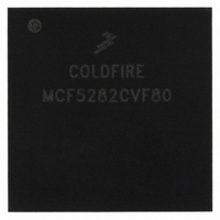
MCF5282CVF80 Freescale Semiconductor, MCF5282CVF80 Datasheet - Page 656

MCF5282CVF80
Manufacturer Part Number
MCF5282CVF80
Description
IC MPU 32BIT 66MHZ 256-MAPBGA
Manufacturer
Freescale Semiconductor
Series
MCF528xr
Datasheet
1.MCF5216CVM66J.pdf
(766 pages)
Specifications of MCF5282CVF80
Core Processor
Coldfire V2
Core Size
32-Bit
Speed
80MHz
Connectivity
CAN, EBI/EMI, Ethernet, I²C, SPI, UART/USART
Peripherals
DMA, LVD, POR, PWM, WDT
Number Of I /o
142
Program Memory Size
512KB (512K x 8)
Program Memory Type
FLASH
Ram Size
64K x 8
Voltage - Supply (vcc/vdd)
2.7 V ~ 3.6 V
Data Converters
A/D 8x10b
Oscillator Type
External
Operating Temperature
-40°C ~ 85°C
Package / Case
256-MAPBGA
Controller Family/series
ColdFire
Ram Memory Size
64KB
Embedded Interface Type
CAN, I2C, SPI, UART
No. Of Pwm Channels
8
Digital Ic Case Style
MAPBGA
Rohs Compliant
No
Package
256MA-BGA
Device Core
ColdFire
Family Name
MCF528x
Maximum Speed
80 MHz
Operating Supply Voltage
3.3 V
Data Bus Width
32 Bit
Number Of Programmable I/os
150
Interface Type
CAN/Ethernet/I2C/QSPI/UART
On-chip Adc
8-chx10-bit
Number Of Timers
12
Lead Free Status / RoHS Status
Contains lead / RoHS non-compliant
Eeprom Size
-
Available stocks
Company
Part Number
Manufacturer
Quantity
Price
Company:
Part Number:
MCF5282CVF80
Manufacturer:
FREESCALE
Quantity:
12 388
Company:
Part Number:
MCF5282CVF80
Manufacturer:
Freescale Semiconductor
Quantity:
10 000
Company:
Part Number:
MCF5282CVF80J
Manufacturer:
Freescale Semiconductor
Quantity:
10 000
- Current page: 656 of 766
- Download datasheet (9Mb)
Debug Support
enabled when interrupt sampling occurs. For address and data breakpoints, reporting is considered
imprecise because several instructions may execute after the triggering address or data is detected.
As soon as the debug interrupt is recognized, the processor aborts execution and initiates exception
processing. This event is signaled externally by the assertion of a unique PST value (PST = 0xD) for
multiple cycles. The core enters emulator mode when exception processing begins. After the standard
8-byte exception stack is created, the processor fetches a unique exception vector, 12, from the vector
table.
Execution continues at the instruction address in the vector corresponding to the breakpoint triggered. All
interrupts are ignored while the processor is in emulator mode. The debug interrupt handler can use
supervisor instructions to save the necessary context such as the state of all program-visible registers into
a reserved memory area.
When debug interrupt operations complete, the RTE instruction executes and the processor exits emulator
mode. After the debug interrupt handler completes execution, the external development system can use
BDM commands to read the reserved memory locations.
If a hardware breakpoint such as a PC trigger is left unmodified by the debug interrupt service routine,
another debug interrupt is generated after the completion of the RTE instruction.
30.6.1.1 Emulator Mode
Emulator mode is used to facilitate non-intrusive emulator functionality. This mode can be entered in three
different ways:
While operating in emulation mode, the processor exhibits the following properties:
The RTE instruction exits emulation mode. The processor status output port provides a unique encoding
for emulator mode entry (0xD) and exit (0x7).
30.6.2
The debug module supports concurrent operation of both the processor and most BDM commands. BDM
commands may be executed while the processor is running, except those following operations that access
processor/memory registers:
For BDM commands that access memory, the debug module requests the processor’s local bus. The
processor responds by stalling the instruction fetch pipeline and waiting for current bus activity to
30-38
•
•
•
•
•
•
•
Setting CSR[EMU] forces the processor into emulator mode. EMU is examined only if RSTI is
negated and the processor begins reset exception processing. It can be set while the processor is
halted before reset exception processing begins. See
A debug interrupt always puts the processor in emulation mode when debug interrupt exception
processing begins.
Setting CSR[TRC] forces the processor into emulation mode when trace exception processing
begins.
All interrupts are ignored, including level-7 interrupts.
If CSR[MAP] = 1, all caching of memory and the SRAM module are disabled. All memory
accesses are forced into a specially mapped address space signaled by TT = 0x2, TM = 0x5 or 0x6.
This includes stack frame writes and the vector fetch for the exception that forced entry into this
mode.
Read/write address and data registers
Read/write control registers
Concurrent BDM and Processor Operation
MCF5282 and MCF5216 ColdFire Microcontroller User’s Manual, Rev. 3
Section 30.5.1, “CPU
Halt.”
Freescale Semiconductor
Related parts for MCF5282CVF80
Image
Part Number
Description
Manufacturer
Datasheet
Request
R
Part Number:
Description:
Mcf5282 And Mcf5216 Coldfire Microcontroller Userís Manual
Manufacturer:
Freescale Semiconductor, Inc
Datasheet:
Part Number:
Description:
Manufacturer:
Freescale Semiconductor, Inc
Datasheet:
Part Number:
Description:
Manufacturer:
Freescale Semiconductor, Inc
Datasheet:
Part Number:
Description:
Manufacturer:
Freescale Semiconductor, Inc
Datasheet:
Part Number:
Description:
Manufacturer:
Freescale Semiconductor, Inc
Datasheet:
Part Number:
Description:
Manufacturer:
Freescale Semiconductor, Inc
Datasheet:
Part Number:
Description:
Manufacturer:
Freescale Semiconductor, Inc
Datasheet:
Part Number:
Description:
Manufacturer:
Freescale Semiconductor, Inc
Datasheet:
Part Number:
Description:
Manufacturer:
Freescale Semiconductor, Inc
Datasheet:
Part Number:
Description:
Manufacturer:
Freescale Semiconductor, Inc
Datasheet:
Part Number:
Description:
Manufacturer:
Freescale Semiconductor, Inc
Datasheet:
Part Number:
Description:
Manufacturer:
Freescale Semiconductor, Inc
Datasheet:
Part Number:
Description:
Manufacturer:
Freescale Semiconductor, Inc
Datasheet:
Part Number:
Description:
Manufacturer:
Freescale Semiconductor, Inc
Datasheet:
Part Number:
Description:
Manufacturer:
Freescale Semiconductor, Inc
Datasheet:


